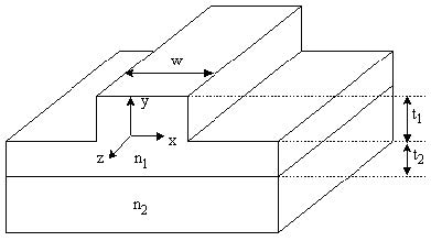
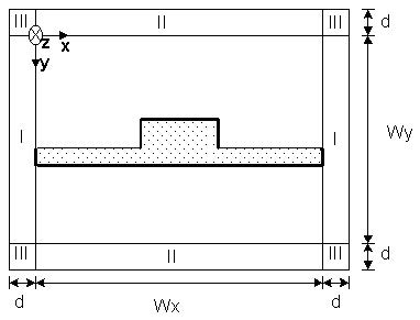
We consider a longitudinal varying 3-D optical waveguide, as shown in Figure 1, and the transverse cross-section of the optical waveguide surrounded by PML regions I, II, and III with thickness d, as shown in Figure 2, where x and y are the transverse directions and z is the propagation direction.
Figure 1: Longitudinally varying 3-D optical waveguide
Figure 2: Transverse cross-section of optical waveguide surrounded by PML
For most anisotropic materials, such as LiNbO3, if the crystal axes of orientation and the applied modulation fields are arranged properly, the dielectric tensor can take the form [12]:
![]()
where ε˜t is an arbitrary 2×2 tensor given by:
![]()
The PML essentially achieves a reflectionless absorption of electromagnetic waves in the continuum limit as the mesh discretization size gets to zero. The absorption inside the PML operates through conductive losses, so that an exponential decay for the field inside the PML is obtained. Therefore, when a PML region surrounds the computational domain, the spurious reflection from the grid boundaries can be made exponentially smaller. It is demonstrated that PML is extremely effective in absorbing out-going traveling waves of a wide special spectrum [1]. Here we will use PML based on the analytic continuation of Maxwell’s equations to a complex variables domain [2]. Closed-form solutions for the fields inside a PML region can be obtained by noting that closed-form solutions existing for Maxwellian fields in real space, map directly to the complex space through this analytic continuation. The general effect of this analytical continuation is to alter the eigenfunctions of MEs so that propagating modes are mapped continuously to exponentially decaying modes, allowing for the reflectionless absorption of electromagnetic waves.
In Cartesian coordinates, this analytical continuation is expressed by the following transformation:

so that

Therefore, the modified source-free Maxwell’s equations can be written as Maxwell’s equations in a complex space:

with

Using Equation 16 in Cartesian coordinate in Equation 20, we get:

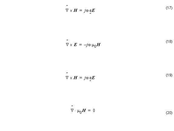
ex , ey , and ez are the unit vectors associated with x , y , and z directions sx , sy , and sz are the parameters associated with the PML boundary condition. Because Equation 17 – Equation 21 are formally the standard Maxwell’s equations except for the change of coordinates, their solutions will be the normal solutions to Maxwell’s equations but with a change of variable according to Equation 15.
Due to complex variables, ζ˜ ( ζ ) are always continuous functions of the real variables ζ for bounded sζ according to Equation 15 (regardless of the continuity of sζ ). The resultant fields inside the PML will be continuous everywhere if the original fields are continuous (the composition of two continuous functions is a continuous function). Boundary conditions, in particular, are preserved by this transformation. The reflectionless property of a PML interface can be easily verified by writing down the TE and TM reflection coefficients, RTE and RTM , for a planar interface and verifying that they are zero. Note that, for a interface (half space problem), only one single complex stretching variable is different from unity (the normal coordinate to the interface). In the corner regions of the computation domain, two or three coordinates need to be stretched simultaneously. The frequency-dependent complex stretching variables sx ( x ) and sy ( x ) are summarized in Table 5.
| Region | Sx | Sy |
| I | 1 | s |
| II | s | 1 |
| III | s | s |
Table 5: Values of sx and sy
Note: See Figure 2 to identify PML regions I, II and III around computational domain.
Since the waves are assumed to propagate in z direction, the parameter sz will be set to unity, while the other PML parameters have to be determined such that the wave impedance of the PML layer placed around the computational domain is exactly the same as that of the adjacent medium inside the computation domain. Hence, the PML medium will perfectly match the computational domain medium allowing the unwanted radiations to leave the computation domain without any reflection.
This necessary condition can be derived as [1]:

where ω is the angular frequency, ε0 and μ0 are the permittivity and permeability of free space, respectively, n is the refractive index for axial anisotropic medium we can chose
εzz = n2 ( z component of the permittivity tensor) and σe and σm are the electric and magnetic conductivities of PML.
The PML impedance matching condition defined by Equation 23 means that the wave impedance of a PML medium equals that of the adjacent medium with refractive index in the computational window
![]() regardless of the angle of propagation or frequency.
regardless of the angle of propagation or frequency.
In the PML medium, we assume an th-power profile of electric conductivity as:

where ρ is the distance inside the PML measured from the PML-computational
domain interface, and d is the width of PML (kept constant in all directions). Using the theoretical reflection coefficient Rt at the interface between the computational window and the PML medium:

The maximum conductivity σmax may be determined as

where c is the light velocity of free space. The parameter s is written as

where λ = 2 π( c ⁄ ω ) , d , x0 , ρ are the free-space wavelength, the PML thickness, the position of the PML surface, and the theoretical reflection coefficient. The PML is terminated with the perfect electric or magnetic conductor. The parameters sx and sy are set in different regions as outlined in Table 6. Inside the orthodox computational domain, both sx and sy are and are set to unit, while for PML regions faced normally with x direction, sx is set as indicated in Equation 26 . With these PML arrangements in different regions, any radiation wave will freely leave the computational domain whatever the angle it hits the PML-computational domain boundaries.


