To insert the input plane, perform the following procedure.
| Step | Action |
| 1 | From the Draw menu, select Input Plane. |
| 2 | To insert the input plane, click as close to the left side of the layout window as possible.
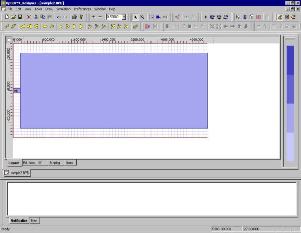
The input plane appears (see Figure 14). |
Figure 14: Input plane
| 3 | To edit the input plane, from the Edit menu, select Properties.
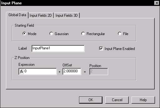
The Input Plane Properties dialog box appears (see Figure 15). |
Figure 15: Input Plane Properties dialog box
| 4 | To position the input plane more accurately, click the Global Data tab. |
| 5 | Under Z Position, type the following value:
Offset: 2.0 Note: The Z Position value should be slightly above 0. |
| 6 | Click the Input Fields 2D tab. |
| 7 | Click Edit.
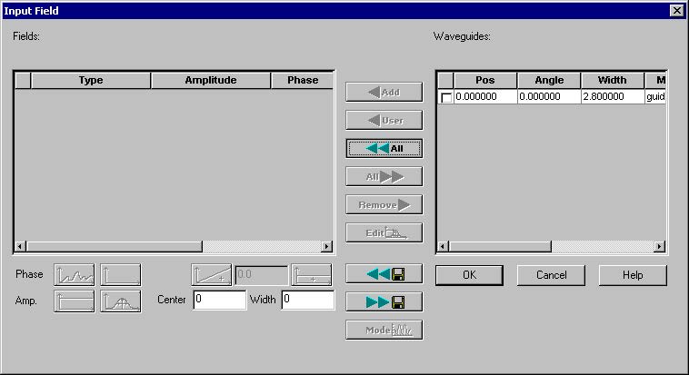
The Input Field dialog box appears (see Figure 16). |
Figure 16: Input Field dialog box
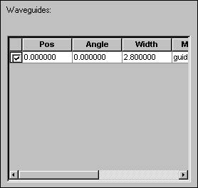
| 8 | In the window under Waveguides, select the check box (see Figure 17) |
Figure 17: Item in Waveguides window
| 9 | Click Add.
The item under Waveguides moves into the window under Fields. |
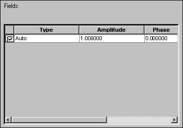
| 10 | In the window under Fields, select the item check box (see Figure 18). |
Figure 18: Item in Fields window
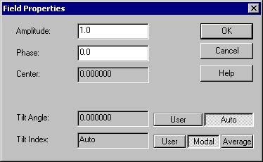
| 11 | To change the default amplitude (1.0) and phase (0.0), click Edit.
The Field Properties dialog box appears (see Figure 19). |
Figure 19: Field Properties dialog box
| 12 | Type the following values (or keep the default values):
Amplitude: 1.0 Phase: 0.0 |
| 13 | To apply the settings and return to the Input Field dialog box, click OK. |
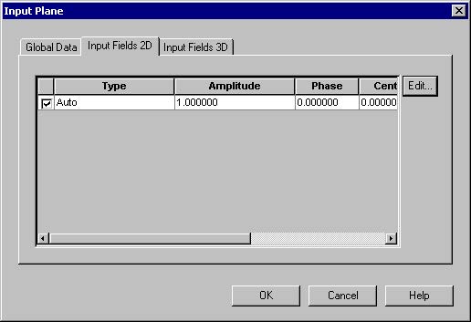
| 14 | To return to the Input Plane dialog box, click OK.
The item appears on the Input Fields 2D tab (see Figure 20). |
Figure 20: Item on Input Fields 2D tab
| 15 | To return to the layout window, click OK. |
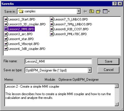
| 16 | To save the project, from the File menu, select Save.
The SaveAs dialog box appears (see Figure 21). |
Figure 21: SaveAs dialog box
| 17 | Type a file name and click Save.
The file is saved and the SaveAs dialog box closes. |


