In this section we show the derivation for the differential equations found in BPM. Of course, more complete accounts of this material can be found elsewhere (see References [1] – [8]). This section exists for the convenience of the user of OptiBPM, to define important terms and illustrate the nature of the different levels of approximation.
The derivation starts with Maxwell’s equations for electromagnetic fields in a continuous medium in the frequency domain. For optical materials it is usually permittivity which differs from the vacuum level. The permeability is unchanged, and so the electromagnetic field is influenced by the device geometry because the refractive index is a function of position. The refractive index distribution n( x, y, z ) enters Maxwell’s equations as a coefficient.

and no charges are present

The magnetic field can be eliminated by taking the curl of Equation 2 and using Equation 3.
![]()
where ![]()
By applying the vector identity
![]()
Equation 6 becomes
![]()
BPM has a bias towards the z axis, so it is natural to treat the z component of both E and ∇ differently than the transverse components, x and y .
Writing

the transverse components of Equation 8 can be written

The divergence Equation 4 can be used to eliminate the longitudinal term above. Equations (9) and (10) can be used to separate the transverse and longitudinal terms in Equation 4

If the refractive index is changing slowly along , then the second term can be neglected. Then the second term on the right hand side of Equation 11 can be replaced with the divergence term of Equation 12.

Using the chain rule on the second divergence term on the right hand side gives a term that cancels the first divergence term, leaving a single term on the right hand side. Also, on the left side, the derivative can be written explicitly

At this point the slowly varying envelope approximation is used, the field components Ex and Ey are varying quickly in the z direction, but are probably varying slowly in x and y . Therefore the substitution
![]()
is likely to result in a function et ( x, y, z ) which is slowly varying in all directions, compared to the wavelength of the light. Of course, a suitable value of Reference Index n0 needs to be used, and often OptiBPM can find by itself an appropriate number. However, sometimes OptiBPM cannot find a good number, and the Reference Index needs to be adjusted manually. It is easy to see if the Reference Index has been set correctly after the simulation is finished. A good value will result in slow variation of the phase of the solution et ( x, y, z ) with respect to z .
Substituting Equation 15 into Equation 14

If the reference index has been set correctly then the first term will be much smaller than the second, and it is safe to neglect the first term. The remaining equation is of first order in z . It is customary to collect the transverse differential operators on the right hand side,

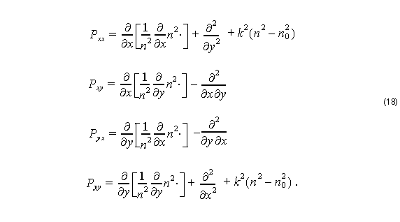
where the components of the operator P are

These are the paraxial vector wave equations for the optical electric field. See Reference [7] for another account of the formulation, and for examples of the use of these equations for simulating waveguide optics with BPM.
In order to solve the system for a practical problem, OptiBPM will apply a mesh to the region where the device is to be simulated. From the device geometry, each point in the mesh is associated with a refractive index, and each point has an electromagnetic field. Equation 17 is a first order equation in z , and so knowledge of the electromagnetic field in some transverse plane ( z = constant) is enough to define an initial value problem. It was assumed since the beginning, with the application of the slowly varying envelope approximation (Equation 1), that the light propagation was in a single direction ( z axis) with no reflection. With Equation 17, it becomes apparent how this simulation is actually carried out. The differential operators P are approximated with finite differences, P is a large sparse matrix, and Equation 17 is applied at a given transverse plane to determine the electromagnetic field at the next transverse plane.

