To define the layout settings, perform the following procedure.
| Step | Action |
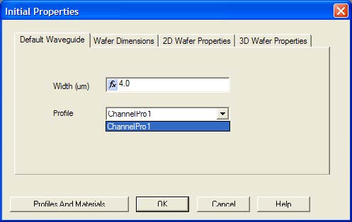
| 1 | In the Initial Properties dialog box, click the Waveguide Properties tab. |
| 2 | Type the following value: Width (um): 4.0 |
| 3 | In the Profile list, click ChannelPro1 (see Figure 4). |
Figure 4: Waveguide Properties tab
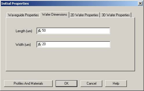
| 4 | Click the Wafer Dimensions tab. |
| 5 | Type the following values (see Figure 5):
Length: 50 Width: 20 |
Figure 5: Wafer Dimensions tab
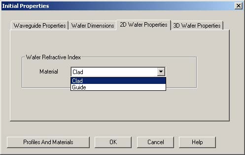
| 6 | Click the 2D Wafer Properties tab. |
| 7 | In the Material list, click Clad (see Figure 6). |
Figure 6: 2D Wafer Properties
| 8 | To apply the settings to the layout, click OK. |
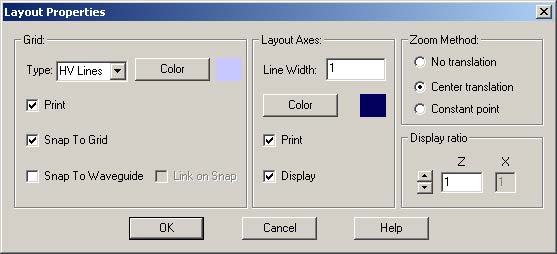
The layout window appears.9From the Preferences menu, select Layout Options.
The Layout Properties dialog box appears (see Figure 7).
Figure 7: Layout Properties dialog box
| 10 | Under Display Ratio, type the following value: Z = 1 |
| 11 | Under Grid, select the Snap to Grid check box. |
| 12 | To apply the settings and return to the main layout, click OK. |


