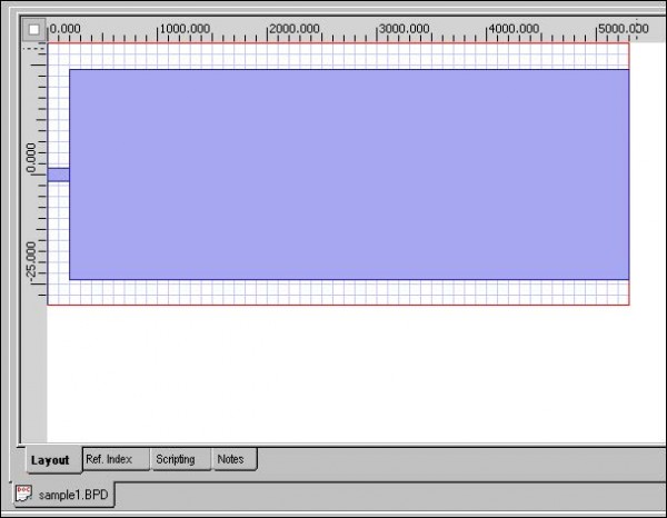
To create an MMI coupler, perform the following procedure.
| Step | Action |
| 1 | From the Draw menu, select Linear Waveguide.
The cursor changes into a cross-hair. |
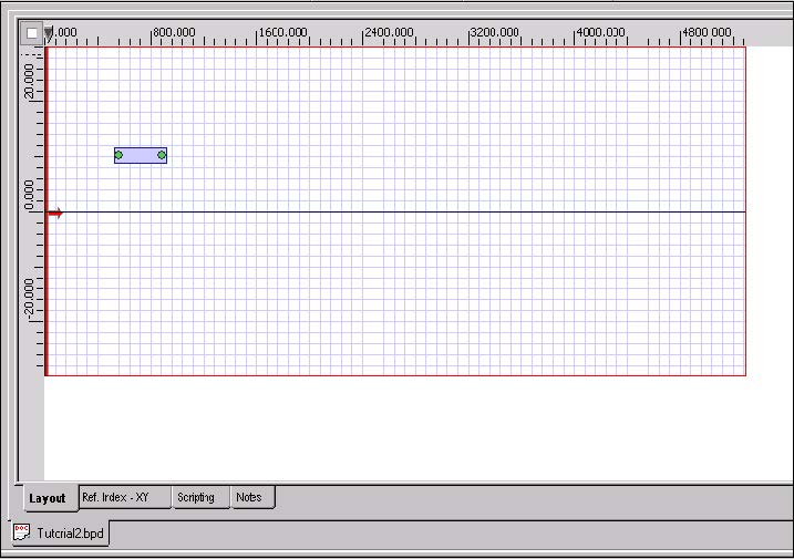
| 2 | To draw the first waveguide, in the layout window, click in the left side of the layout, drag the waveguide towards the right side of the layout window, and release (see Figure 5). |
Figure 5: Drawing the first linear waveguide
| 3 | To edit the waveguide, from the Edit menu, select Properties
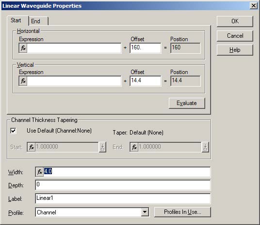
or Double-click the waveguide. The Linear Waveguide Properties dialog box appears (Figure 6). |
Figure 6: Linear Waveguide Properties dialog box
| 4 | Click the Start tab. |
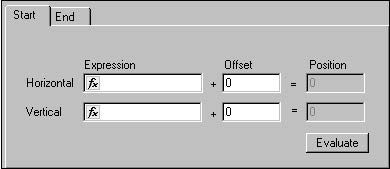
| 5 | Under Offset, type the following values (see Figure 7):
Horizontal: 0 Vertical: 0 |
Figure 7: Start offset values — first waveguide
| 6 | Click the End tab. |
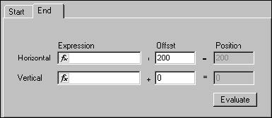
| 7 | Under Offset, type the following values (see Figure 8):
Horizontal: 200 Vertical: 0 |
Figure 8: End offset values — first waveguide
| 8 | To apply the settings, click OK.
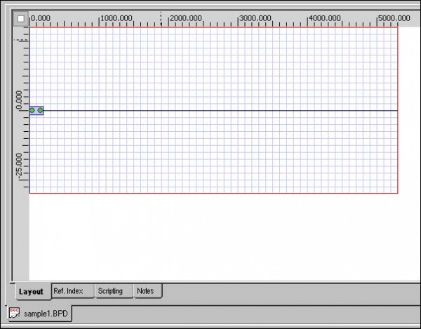
The position and the size of the linear waveguide change according to the settings that you selected (see Figure 9). |
Figure 9: Modified linear waveguide — first
| 9 | To draw the second waveguide, in the layout window, click beside the first waveguide, drag the second waveguide towards the right side of the layout window, and release (see Figure 10). |
Figure 10: Drawing the second linear waveguide
| 10 | To edit the second waveguide, from the Edit menu, select Properties.
The Linear Waveguide Properties dialog box appears. |
| 11 | Click the Start tab. |
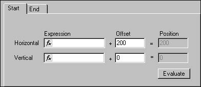
| 12 | Under Offset, type the following values (see Figure 11):
Horizontal: 200 Vertical: 0 |
Figure 11: Start offset values — second waveguide
| 13 | Click the End tab. |
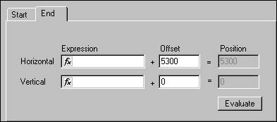
| 14 | Under Offset, type the following values (see Figure 12):
Horizontal: 5300 Vertical: 0 |
Figure 12: End offset values — second waveguide
| 15 | Type the following value:
Width: 48 |
| 16 | To apply the settings, click OK. |
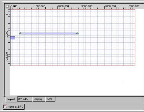
| 17 | The position and the size of the second linear waveguide change according to the settings that you selected (see Figure 13). |
Figure 13: Modified linear waveguide — second


