
To define channels for 2D and 3D profiles, perform the following procedure.
| Step | Action |
| 1 | In the directory under OptiBPM_Designer1, under the Profiles folder, right-click the Channel folder.
A context menu appears. |
| 2 | Select New.
The ChannelPro1 dialog box appears. Note: To ensure that you can view all fields, maximize the ChannelPro1 dialog box. |
| 3 | Keep the default Profile name: ChannelPro1 |
| 4 | To define the 2D profile definition:
• Under 2D profile definition, in the Material list, click Silica Core. By selecting Silica Core, if the 2D simulator is called, any point inside a waveguide associated with the profile name ChannelPro1 will have the refractive index as defined in Silica Core. |
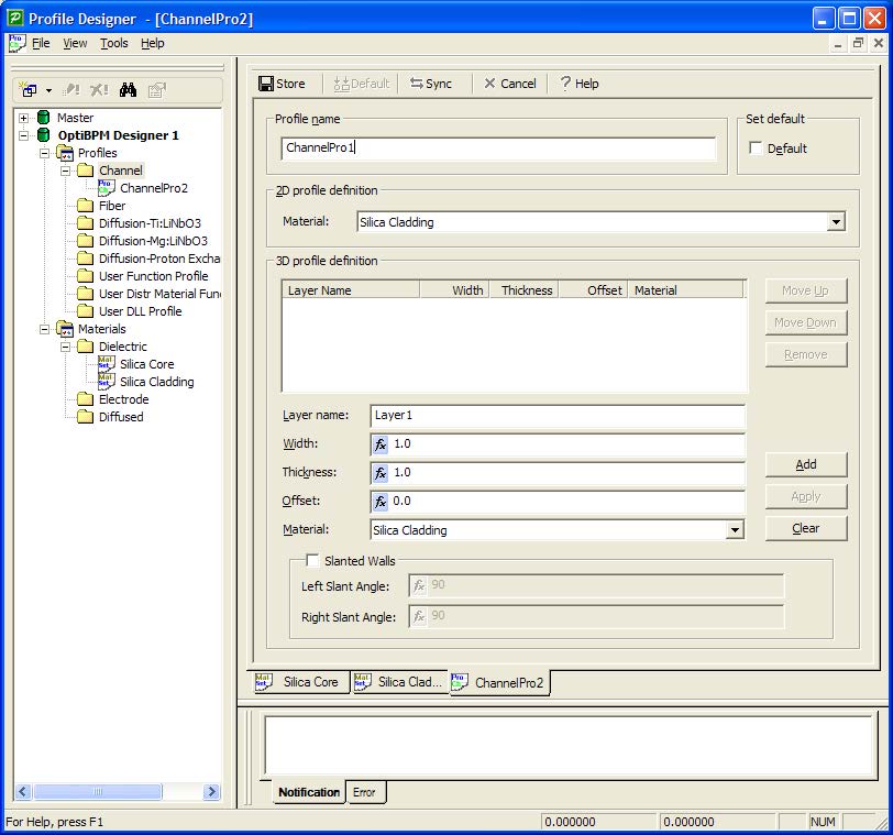
Figure 9: 2D profile definition
| Channel profiles consist of layers in the epitaxial direction, and these layers are defined in the 3D profile panel. | |
| 5 | To define the 3D profile definition:
a. Under 3D profile definition, type the following information: Layer name: Channel Width: 4.0 Thickness: 2 Offset: 0 b. In the Material list, click Silica Core. c. Click Add. The information you typed appears in the 3D profile definition window. |
| 6 | To save the channel profile, click Store.
ChannelPro1 appears in the Channels folder in the directory, in the Profile Designer title bar, and on the tab at the bottom of the layout (see Figure 10). |
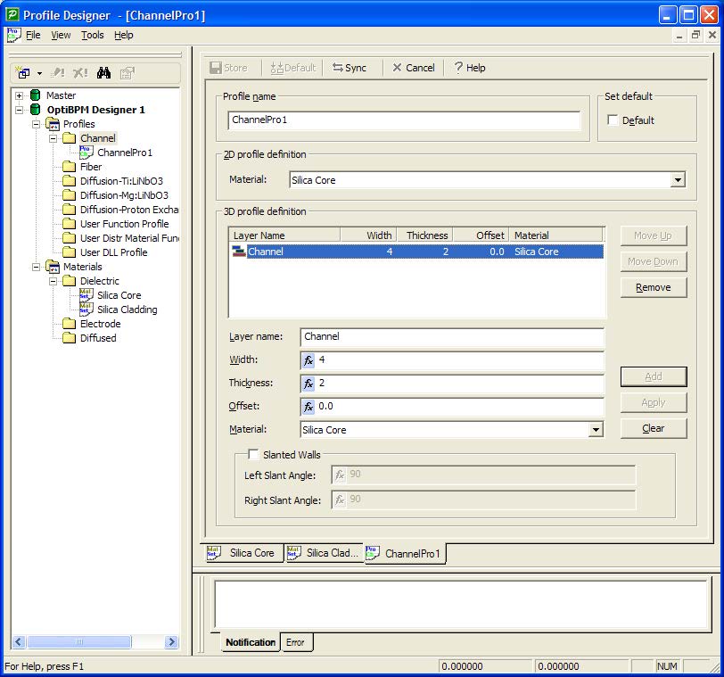
Figure 10: Defined Channel profile
| 7 | In the directory under OptiBPM_Designer1, under the Profiles folder, right-click the Fiber folder.
A context menu appears. |
| 8 | Select New.The FiberPro1 dialog box appears.
Note: To ensure that you can view all fields, maximize the FiberPro1 dialog box. |
| 9 | Keep the default Profile name: FiberPro1 |
| 10 | To define the 2D profile definition:
• Under 2D profile definition, in the Material list, click Silica Core. |
| 11 | For the 3D definition of the Fiber profile, the layers are now concentric layers of an optical fiber. To define the 3D profile definition:
a. Under 3D profile definition, type the following information: Layer name: Fiber Core Rx: 2.0 Ry: 2.0 b. In the Material list, click Silica Core. c. Click Add. The information you typed appears in the 3D profile definition window. |
| 12 | To save the fiber profile, click Store.
FiberPro1 appears in the Fiber folder in the directory, in the Profile Designer title bar, and on the tab at the bottom of the layout (see Figure 11). |
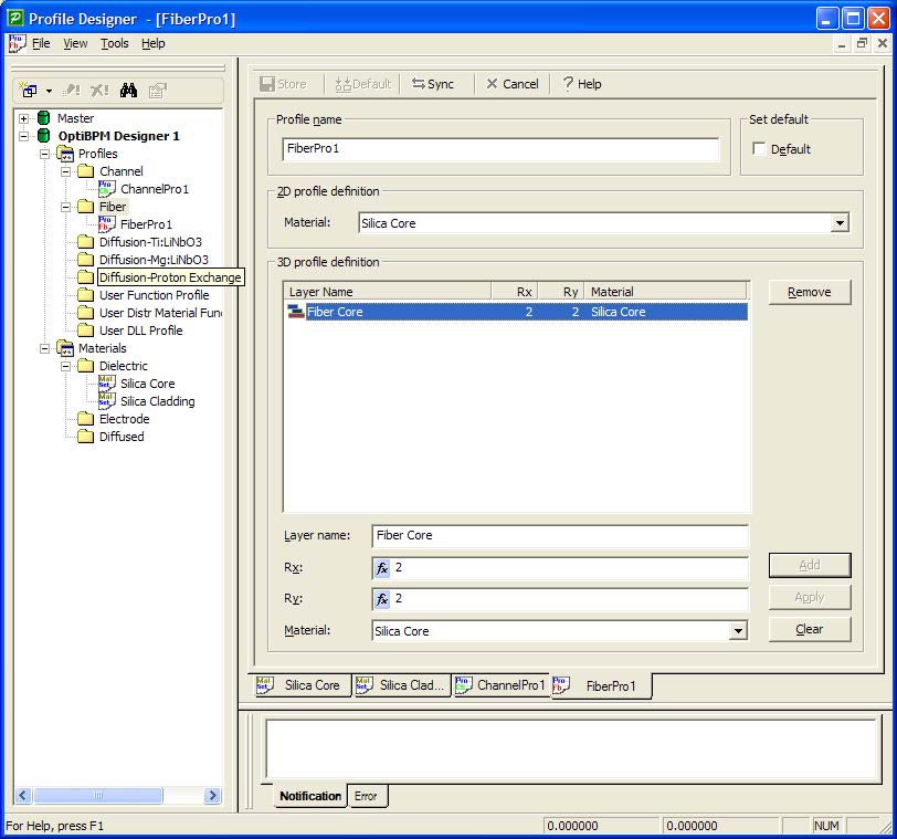
Figure 11: Defined fiber profile
| 13 | To return to the OptiBPM Layout Designer window, minimize the Profile Designer window.
The OptiBPM GUI and Initial Properties dialog box appear. |
In the Waveguide Properties tab, the Profiles drop-down box, the two profiles we have defined are available.