In this example, we show that the Gain Flattening type of optimization can be used to design multi-wavelength pumped Raman amplifiers with a flattened gain. Given amplifier specifications such as signal level, required gain profile, and number of allowed pump channels, the optimization procedure can generate a combination of pump wavelengths and input powers that would result in the gain profile approximating the specified one as close as possible.
Note that this optimization may require a huge number of iteration since interaction between channels and pumps are very complicated. Therefore it is very important to give good estimated initial values, especially for pump wavelengths, to the optimizer to lower the required number of iterations. For example, a general guideline to estimate the pump channel locations is given in [1].
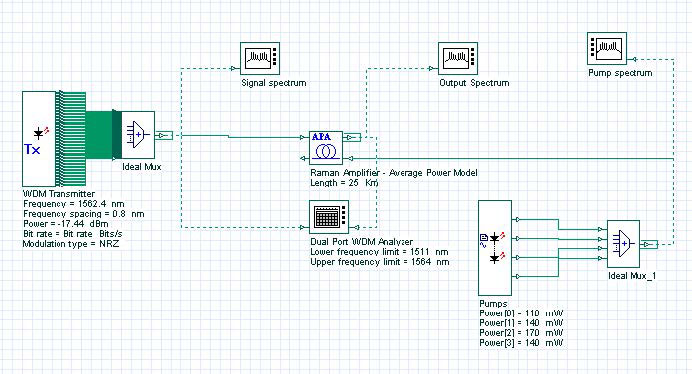
Figure 1: Multi-pump configuration project layout
The project is Optimizing the pump power and frequencies Average Model.osd. It contains two versions of the same project, named Initial with the initial pump configuration and Optimized with the optimized pump configuration and a MPO setup.
The project layout is as shown in Figure 1. 64 channels between 1512 and 1562.4 nm with 0.8 nm separations are multiplexed. The average power of each channel is -20 dBm. We have used our Average Power Raman amplifier model to simulate the amplifier. This model allows a fast and accurate estimation of the amplifier gain. For more information on this model please refer to component description. The fiber used as gain medium is a 25 km fiber with 9.5e-014 m/W peak Raman gain coefficient. The effective area of the fiber is 55 micron square. The loss of the fiber is 0.2 dB/km. We are only interested in the frequency domain response of the amplifier. Therefore, we have done the simulation with Parameterized signals. To do so, we have selected Parameterized option from Signals tab of the Initial Parameters window. To set the upper pump frequency, go to Enhanced tab of the Raman Amplifier component and set Upper pump reference parameter to 1510 nm. In this example, a Dual Port WDM Analyzer measures amplifier gain and gain flatness. To limit the measurement window within signal spectrum, we set lower and upper frequency limits from the Main tab of Dual Port WDM Analyzer properties dialog box. These values are 1511 nm and 1564 nm, respectively.
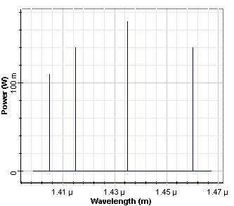
Four CW pump signals with initial powers shown in Figure 2 are used for backward pumping. Initial wavelengths and powers of these pumps are also given in Table 1. These parameters are chosen as in [2] for comparison. Initial configuration is shown in the Layout named “Initial”.
Figure 2: Initial pump power allocation
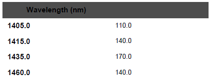
Table 1: Initial pump parameters
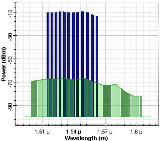
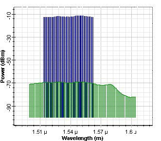
With this initial pump configuration, we observed the output power spectrum as shown in Figure 3. The obtained gain flatness was 4 dB, maximum forward gain was 10.5 dB. These values can be seen by double clicking on Dual Port WDM Analyzer. To see the gain flatness (Ratio max/min Gain in dB) and maximum forward gain (Max Value Gain in dB), go to Details tab of this component.
Figure 3: Output power spectrum before the optimization
The optimized configuration is shown in the Layout named “Optimized”. In the optimization setup. We have selected the Gain Flattening type of optimization in the Main tab. In the Parameters tab, pump powers and frequencies are added to the table. Minimum and maximum pump powers are selected to be 0 and 300 mW, respectively. Minimum and maximum pump wavelengths are selected to be 1400 nm and 1500 nm, respectively. In the Results tab, we selected the Gains for all channels from dual port WDM analyzer to add the table. Target gain is 10.0 dB as inserted in Target Value of this tab. Number of Goals to Achieve Exactly is same as the number of channels and automatically set.
In the Constraints tab, we have added Gain Flatness (Ratio Max/Min Gain) as a constraint. Gain flatness is measured by the Dual Port WDM Analyzer. As a constraint, gain flatness less than 1.5 dB is required. As an extra constraint, we limit the total pump power to between 500 mW and 1000 mW. This is required to make sure that we can get a gain as high as required. Without forcing this constraint, we have seen that amplifier can be optimized with good gain flatness, but with a gain of about 4 dB. Note also that no unit for parameters and results is indicated in the optimization tool. The units of parameters and results in optimization tool are taken to be same as the ones that are given in project layout for the corresponding parameter or result.
In the Advanced tab, Result Termination Tolerance is 0.1, Constraint Termination Tolerance is 0.1, and Parameter Termination Tolerance is 0.1.
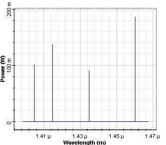
Optimum pump powers and wavelengths are obtained after 32 calculations. Pump power spectrum after the optimization is shown in Fig. 4. Optimum pump parameters are also shown in Table 2. Also note that, there is not a unique set of optimum parameters. Therefore, optimization procedure can obtain different set of parameters depending on the starting parameter values.
Figure 4: Pump power spectrumn
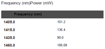
Table 2: Optimum pump parameters
For this specific example, we have found that for the given set of requirements, optimization procedure only needs to adjust the pump powers. As can be seen from Table 2, pump frequencies are kept at the original values. As stated before, there is not a unique set of optimum parameters.
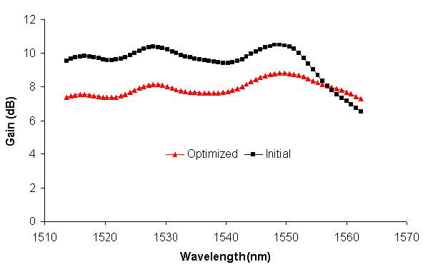
Output power spectrum after the optimization is shown in Figure 5. Gain flatness achieved in [2] was ~2.6 dB. We have observed a better gain flatness, comparing to this value. After the optimization, achieved forward gain flatness is 1.5 dB, maximum forward gain is ~9 dB. Initial and optimized gain spectrums are shown in Figure 6 for comparison.
Figure 5: Output power spectrum after the optimization
Figure 6: Gain spectrums, before and after optimization is applied
References:
[1]Y. Emori, et al., “Broadband flat-gain and low-noise Raman amplifiers pumped by wavelength-multiplexed high power laser diodes”, Opt. Fib. Tech. 8, 107 (2002).
[2]M. Yan, et al., “Automatic design scheme for optical fiber Raman amplifiers backward pumped with multiple laser diode pumps”, IEEE Photon. Tech. Lett. 13, 948 (2001).


