In this tutorial, we provide a basic example of Goal Attainment optimizations. In this example we will use the optimization tool in the context of parameter extraction. Thermal noise parameter of PIN will be extracted to get a receiver sensitivity of -17 dBm.
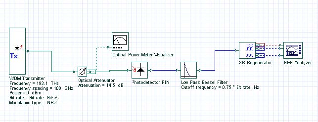
The design layout is shown in Figure 1. The transmitter power is selected to be 0 dBm. The bit rate is 10 Gbps and average received power is about -17 dBm when attenuation is 14.5 dB.
Figure 1: Project layout for the extraction of thermal noise parameter of PIN
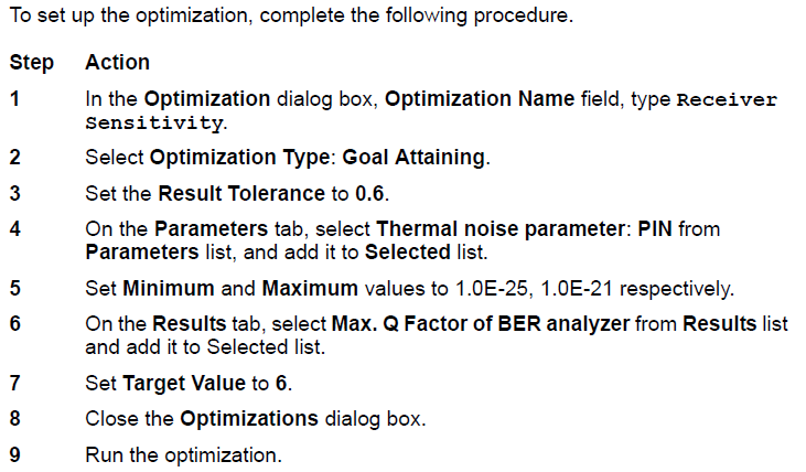
Setting up the optimization

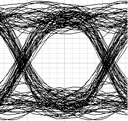
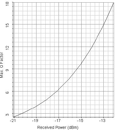
After about 3 passes, the optimizer will find the Thermal noise parameter to get a Q factor of 6 when received average power is -17 dBm. The proper Thermal noise is found to be 5E-22 W/Hz. The eye diagram in this case is shown in Figure 2. Figure 3 shows the Max. Q factor, respect to received power. This figure is obtained by sweeping the transmitter power from -3 dBm to 4 dBm.
Figure 2: Thermal noise factor of PIN is 5E-22 W/Hz with received average signal power -17 dBm
Figure 3: Max. Q factor vs. received power


