The system demonstrates an electrical phase-locked loop.
Sample: EPLL.osd
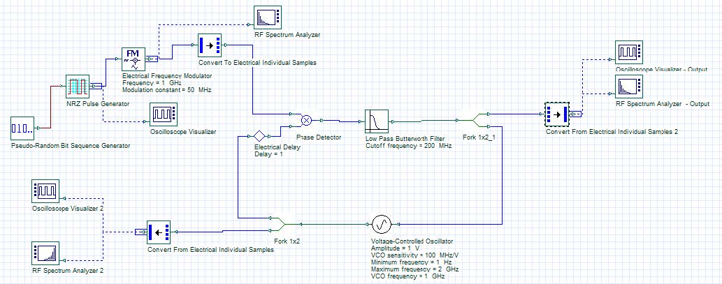
The layout presented in the figure below is PLL system configured with a phase detector, a low pass filter and a voltage controlled oscillator. This example shows the response of a PLL to a sequence of pulses modulated in frequency to an electrical carrier at 1GHz.
Figure 1: PLL system
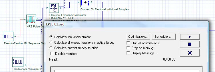
Since the single sample signals are used in this configuration, we can disable the display messages in the calculation window, as demonstrated in the figure below and the simulation will be faster.
Figure 2: Calculation window
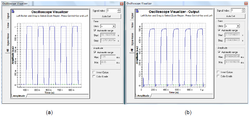
After running the simulation, the following results were obtained
Figure 3: (a) Input sequence and (b) output sequence recovered by PLL


