In this section, we will show how dispersion compensation schemes affect the system performance. The pulse broadening effect of chromatic dispersion causes the signals in the adjacent bit periods to overlap. This is called intersymbol interference (ISI). Broadening is a function of distance as well as dispersion parameter D. The dispersion parameter is given in ps/nm/km and changes from fiber to fiber. It is also a function of wavelength. D is usually about 17 ps/nm/km in the 1.55 μm wavelength range for a standard single mode fiber (SMF). It is at a maximum of 3.3 ps/nm/km in the same window for a dispersion-shifted fiber (DSF). Nonzero dispersion fiber (NDF) has a chromatic dispersion between 1 and 6 ps/nm/km or -1 and -6 ps/nm/km.
For externally modulated sources, transmission distance limited by chromatic dispersion is [1]

When D=16 ps/(km-nm) and at 2.5 Gbps, L ≈ 500km, whereas it drops to 30 km at 10 Gbps bit rate.
Several techniques, including Dispersion Compensating Fiber or Fiber Bragg Grating, can be used to compensate the accumulated dispersion in the fiber. In the following example we will show three different schemes, pre-, post-, and symmetrical compensation, to compensate the fiber dispersion. First we will use dispersion compensating fibers (DCFs). We will then show how the amount of accumulated dispersion from the dispersion compensator affects the performance. In this case, we will use an ideal dispersion compensating module (DCM) as the dispersion compensator to show the idea.
Pre-, post-, and symmetrical-compensation by using DCF
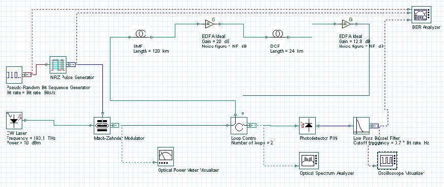
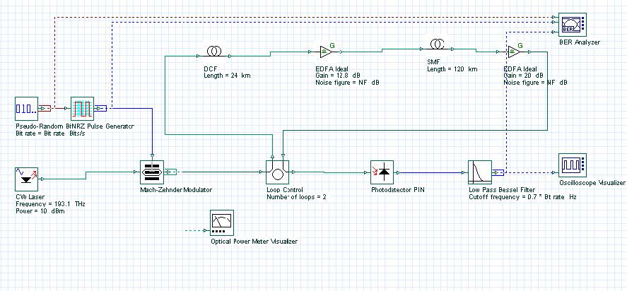
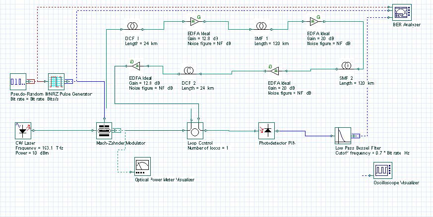
Pre-, post-, and symmetrical compensation configurations are shown in Figure 1, Figure 2, and Figure 3. In our simulations, we have used optical amplifiers after each fiber to compensate for the span loss. The dispersion parameter of SMF is 120 km long and 16 ps/nm-km. Therefore, total accumulated dispersion is 16×120 = 1920 ps/nm. This much dispersion can be compensated by using a 24 km long DCF with -80 ps/km-nm dispersion. Total transmission distance is 120×2 =240 km for each cases. In the post-compensation case, DCF is placed after SMF. In the symmetrical compensation case, fiber placement follows the sequence of SMF, DCF, DCF, SMF.
Figure 1: Dispersion post-compensation
Figure 2: Dispersion pre-compensation
Figure 3: Dispersion symmetrical-compensation
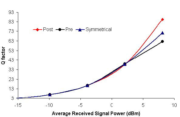
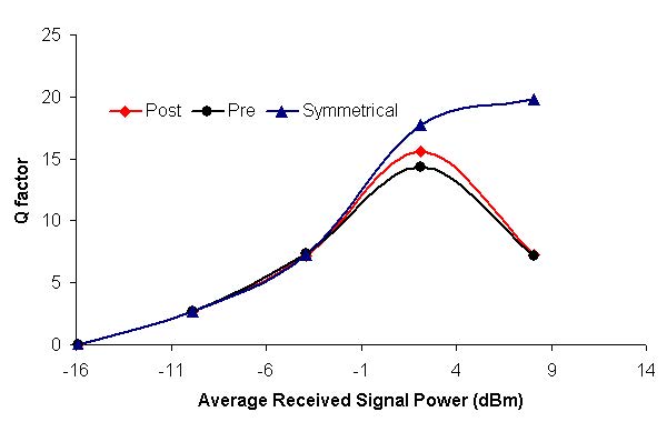
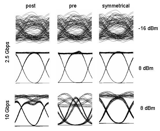
For these three cases, the project is found in the following file: Dispersion compensation pre post symmetrical.osd. In these simulations, we have used NRZ modulation formats. Receiver sensitivity is -28 dBm for 2.5 Gbps and -25 dBm for 10 Gbps. (Thermal noise of the PIN is 2.048e -23W/Hz.) Simulation results are shown in Figure 4 and Figure 5. Figure 4 shows Q factor of received signal versus transmitted signal power for these three schemes at 2.5 Gbps bit rate. Figure 5 shows the same graph for the 10 Gbps bit rate. To simulate the designs in 10 Gbps, you need to set the global parameter bit rate to 10 Gbps. From these figures, we can conclude that the best performance is obtained by using symmetrical dispersion compensation. The worst case is dispersion pre-compensation. This can also be seen from the eye diagrams given in Figure 5. These results are in complete agreement with the results found in the literature [2] [3].
Figure 4: Q factor verses signal power at 2.5 and 10 Gbps bit rates for pre-, post-, and symmetrical dispersion compensations
Figure 5: System performance at 2.5 and 10 Gbps bit rates for pre-, post-, and symmetrical dispersion compensations. The eye diagrams are shown for -12 and 10 dBm signal powers.
Dispersion compensation by using DCM
We will now show how the amount of compensating dispersion affects system performance. We will use an Ideal Dispersion Compensation FBG as the dispersion compensation module (see Figure 6). In this case, we selected a post-compensation scheme because it is simple compared to the symmetrical compensation scheme. All schemes perform similar in low power regions. Project is given in Dispersion compensation post with FBG.osd.
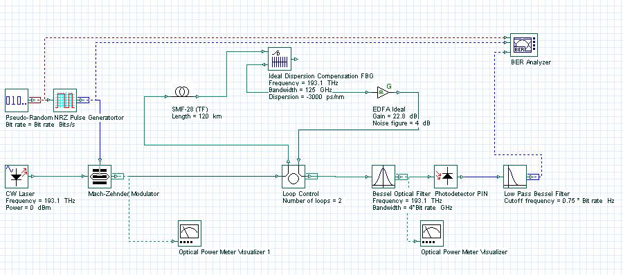
Figure 6: Dispersion compensation by using DCM
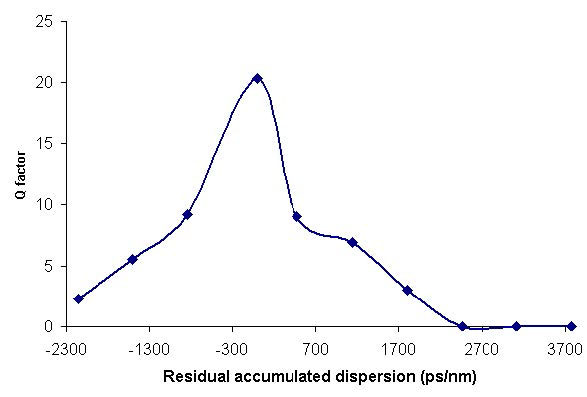
The total accumulated dispersion of the SMF is 16×120 = 1920 ps/nm. We swept the total dispersion of FBG from -30 to -3000 ps/nm. The bit rate is set to 10 Gbps. In this simulation, we want to investigate the dispersion-limited performance of the system. To avoid triggering fiber nonlinearity, we keep the received power at -3 dBm. Effects of residual dispersion to nonlinear effects will be considered in other examples. Figure 7 shows Q factor versus residual dispersion. This simulation shows that in the linear regime (low power), completely compensating fiber dispersion gives the best result. Over-compensating degrades the system performance.
Figure 7: Q-factor versus residual dispersion
References:
[1]G. P. Agrawal, Fiber Optic Communication Systems, Wiley-Interscience, 1997.
[2]R. Ramaswami and K. N. Sivarajan, Optical Networks: A practical Perspective, Morgan Kaufmann, 1998.
[3]M. I. Hayee and A. E. Willner, “Pre- and post-compensation of dispersion and nonlinearities in 10-Gb/s WDM systems”, IEEE Photon. Tech. Lett. 9, pp. 1271, 1997.


