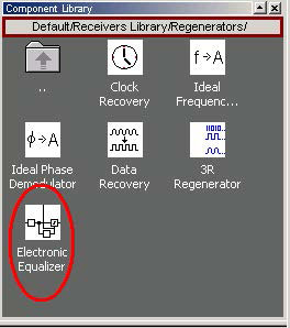
Project DFE Application.osd demonstrates the application of the component ‘Electronic Equalizer”. The Electronic Equalizer component is available in the OptiSystem component library folder ‘Default/Receivers Library/Regenerators’ (Figure 1).
Figure 1: OptiSystem component library
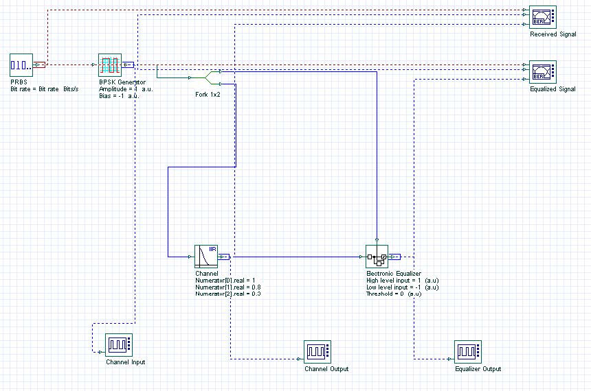
The system layout is presented in Figure 2. A 10 GB/s BPSK signal is generated by the ‘BPSK Generator’ component. The signal is then applied to a propagation channel. The propagation channel is an IIR filter with coefficients [1 0.8 0.3], that simulates a time dispersive channel that causes intersymbol interference (ISI). The signal is then applied to the electronic equalizer component that will compensate the signal dispersion.
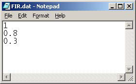
The channel estimation is done in the MLSE equalizer using the same coefficients as the FIR filter. The coefficients are loaded from a text file (FIR.dat -Figure 3).
Figure 2: System layout
Figure 3: Equalizer coefficients after training
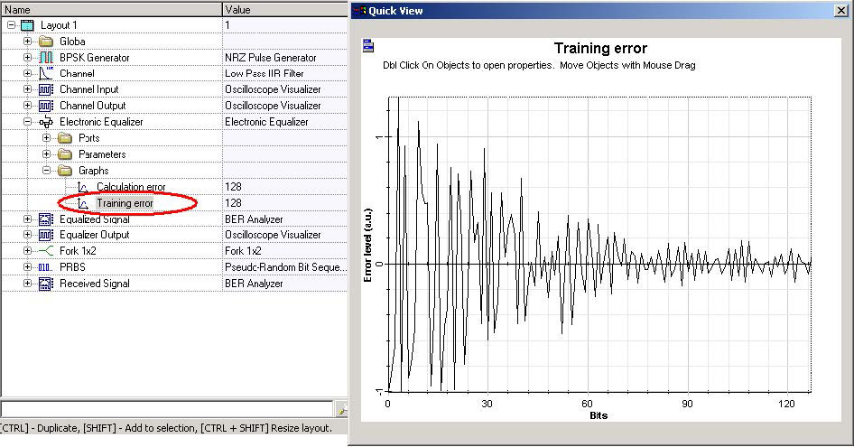
The electronic equalizer will use the original BPSK signal as a training signal to calculate the filter tap coefficients for the FFE and DFE stages. After the calculation, the values of the tap coefficients are available in the parameter Report (Figure 3), and the values for the calculated error during training are available as a graph in the project browser (Figure 4).
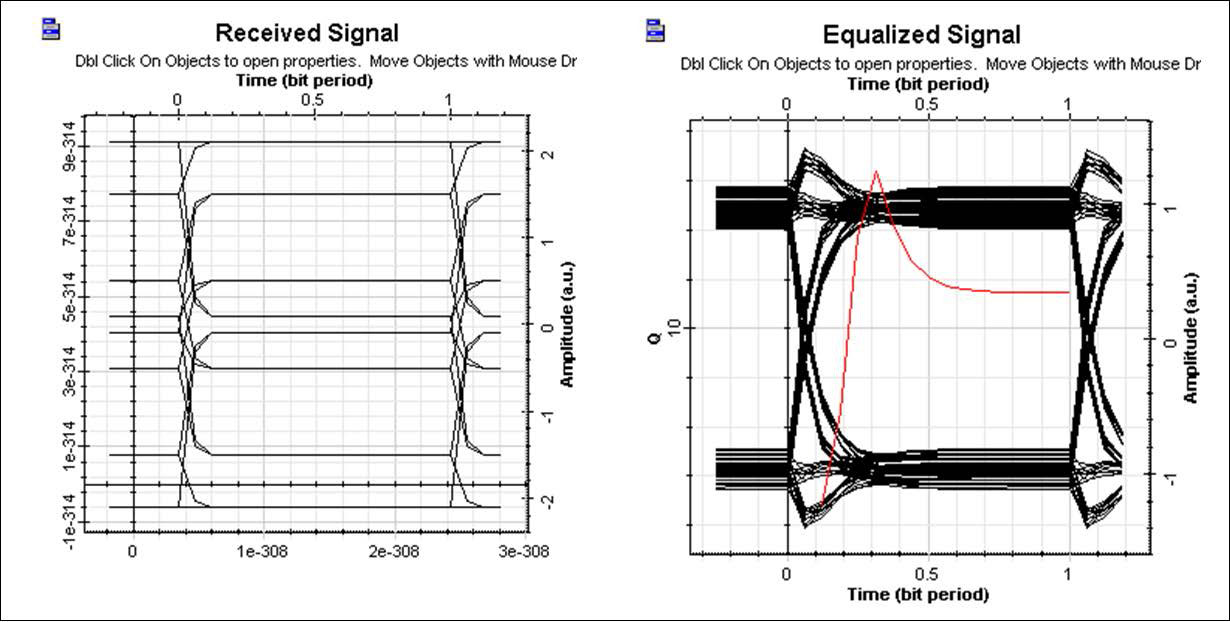
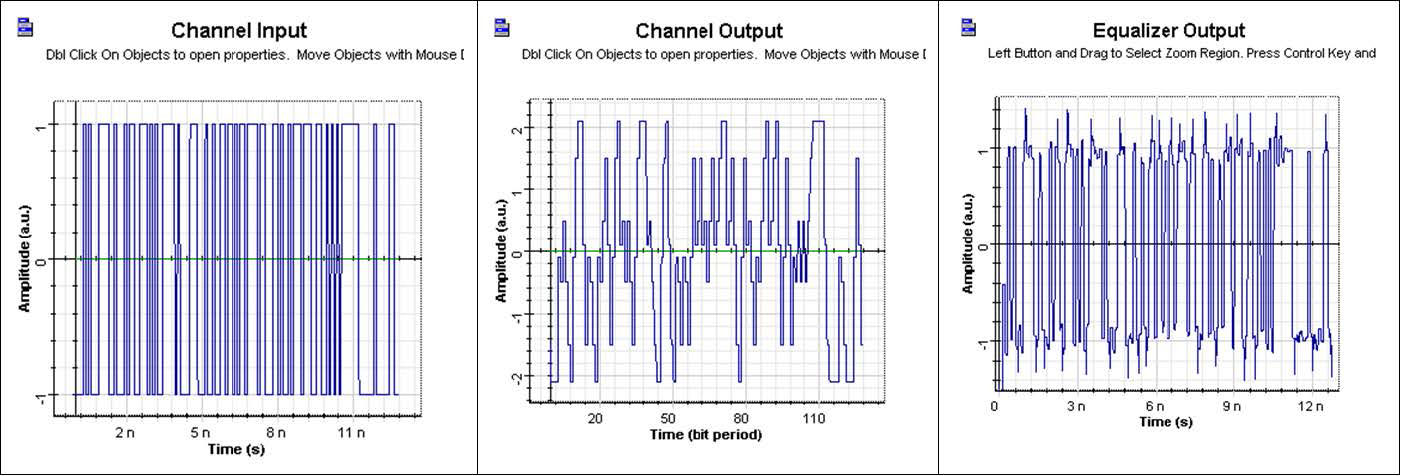
Figure 5 presents the eye diagram before and after the equalizer. Figure 6 presents the signal evolution from the channel input to the equalizer output. The equalizer mitigates ISI and improves the system’s performance.
Figure 4: Error level during training
Figure 5: Eye diagram before and after the equalizer
Figure 6: Signal propagation in the system


