This lesson demonstrates the effect of third-order dispersion on the fundamental and higher-order solitons.
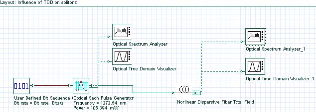
The layout that we use and its global parameters are shown in Figure 1.
Figure 1: System layout with parameters
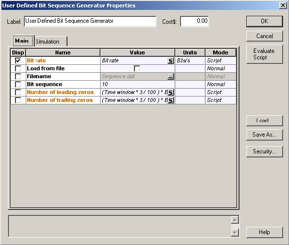
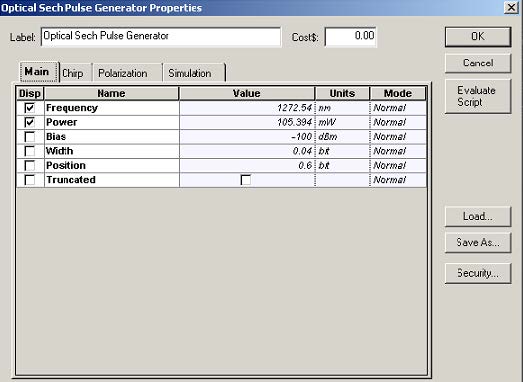
The setups for the bit sequence generator and for the sech-pulse generators are displayed in Figure 2 and Figure 3.
Figure 2: Setup for the bit sequence generator
Figure 3: Setup for the sech-pulse generator
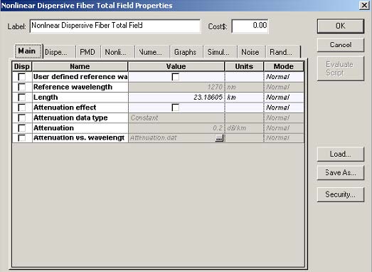
Figure 4 shows the setup for the nonlinear dispersive fiber component.
Figure 4: Setup for the nonlinear dispersive fiber component
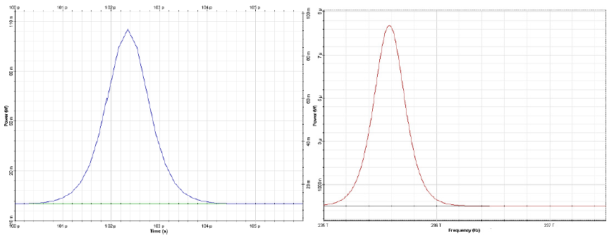
Figure 5: Input pulse shape (left) and spectrum (right)
The input pulse (Figure 1) is a 1 ps wide (FWHM) fundamental soliton propagating near the zero-dispersion wavelength [1].
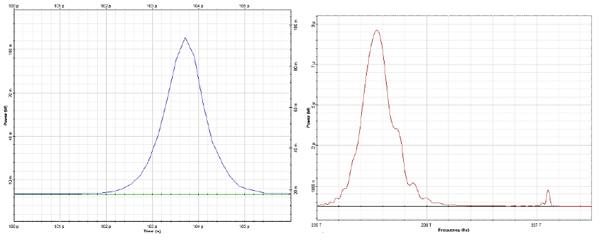
The output pulse shape and spectrum are shown in Figure 6.
The principal effect of the third-order dispersion term is to stimulate radiation resonantly at a frequency:

Figure 6: Output (at 10 soliton periods or 23.18 km) pulse shape (left) and spectrum (right). Resonance radiation peak is evident
Good agreement can be seen between the results presented in [1] and in Figure 6.
Figure 7: Output pulse shape after 11.6 km (or 5 soliton periods) of propagation. Second order soliton has been split into its constituents by the effect of TOD [1]
The second part of this tutorial considers TOD-induced decay of N=2 soliton. To
simulate this phenomenon, the following changes of the parameters are applied. The
sequence length is set to four bits and the samples per bit parameter is set to 1024.
The bit sequence in the user defined bit sequence generator is changed to “0100”.
The power of the sech-pulse generator is set to 421.576mW (corresponding to
second order soliton). The fiber length is changed to 11.593km, which corresponds to
five soliton periods. Beta 3 dispersion parameter in the optical fiber component is set
to 0.019366776 ps3/km.
The output pulse shape is presented in Figure 7. The second-order soliton has been split into its constituents by the effect of TOD [1].
References:
[1]P. K. A. Wai, C. R. Menyuk, Y. C. Lee, and H. H. Chen Optics Letters, 11, No. 7, (1986).




![Optical System - Figure 7 - Output pulse shape after 11.6 km (or 5 soliton periods) of propagation. Second order soliton has been split into its constituents by the effect of TOD [1] Optical System - Figure 7 - Output pulse shape after 11.6 km (or 5 soliton periods) of propagation. Second order soliton has been split into its constituents by the effect of TOD [1]](https://optiwave.com/wp-content/uploads/2023/05/Optical-System-Output-pulse-shape-after-11.6-km-or-5-soliton-periods-of-propagation.-Second-order-soliton-has-been-split-into-its-constituents-by-the-effect-of-TOD-1.jpg)