The objective of this lesson is to demonstrate a distributed Raman fiber design.
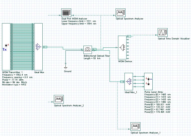
Initially, the system described in Figure 1 was designed.
The system consists of 64 channels at 10 Gbits/s propagating for a 50 km SMF-28 fiber. The attenuation in the fiber is compensated by the Raman amplification due to the 4 backward laser pumps launched in the input port 2.
Figure 1: System layout
The 64 channels are spaced by approximately 100 GHz and go from 1548.92 nm to 1562.4 nm. The input power is -17.44 dBm/channel.
There are 4 pumps and the pump powers and wavelengths were chosen using the optimization tool and the Raman Amplifier-Average power model instead of the Bidirectional Fiber to guarantee a faster optimization.
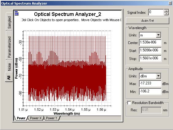
Figure 2 shows the input power spectrum at the input port 1 in the fiber (left input port).
Figure 2: OSA at the Fiber input port 1
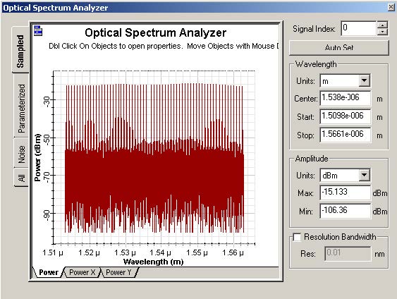
After simulating the system, the output spectrum is shown in Figure 3.
Figure 3: OSA at the Fiber output port 2
As we can see in the WDM analyzer (Figure 4), the average gain in the fiber was 1.27 dB and the gain flatness was 1.5 dB.
Figure 4: WDM Analyzer


