The fundamental limitation to high-speed communication systems over the embedded standard single-mode fiber at 1.55 µm is the linear chromatic dispersion.
Typical value of β2 = –20ps2 / km at 1.55 µm for SMF leads to D=16 ps/(nm.km). For bit rate B = 10 Gb/s, the slot duration is TB = 100 ps. If we consider the duty cycle
0.5 → TFWHM = 50ps → T0 = 30ps
the corresponding dispersion length will be approximately LD ~ 45 km.This lesson compares RZ- and NRZ-modulation format transmission in SMF at 10 Gb/s, taking into account group velocity dispersion, self-phase modulation due to the Kerr nonlinearity, linear losses, and periodical amplification with ASE noise.
Two tasks will be addressed:
• Compare RZ and NRZ format transmission for lossless cases. The results can be compared to the results of [1], Figure 1(a), and Figure 1(b).
• Investigate linear losses and periodic amplification, taking into account ASE noise.
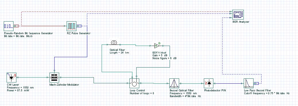
Figure 1(a), and Figure 1(b) show the layouts used for observing the RZ and NRZ modulation formats.
Figure 1:(a) RZ layout — format transmission for lossless case
Figure 1: (b)NRZ layout — format transmission for lossless case
The following global parameters were used:
• Bit rate = 10 Gb/s
• Sequence length = 128 Bits
• Samples per bit = 128
There are no changes in pseudo-random bit sequence generators in either layout. The RZ-generator has following properties:
• Rectangle shape: Gaussian
• Duty cycle = 0.5 bit
• Rise time = 0.15 bit
• Fall time = 0.25 bit
An externally modulated CW Laser with carrier wavelength l = 1550 nm and line width = 0.1 MHz was used as the optical source.
Standard mode optical fiber has the following properties:
Dispersion coefficient

Dispersion slope


Linear losses
α = 0.2 dB/km
Properties of the Bessel optical filter are carrier wavelength λ =1550 nm and bandwidth = 4 x Bit rate. The cutoff frequency of the low pass Bessel electrical filter is 0.75 x Bit rate. Some of above parameters are chosen in accordance with [1], which allows comparison of the results.
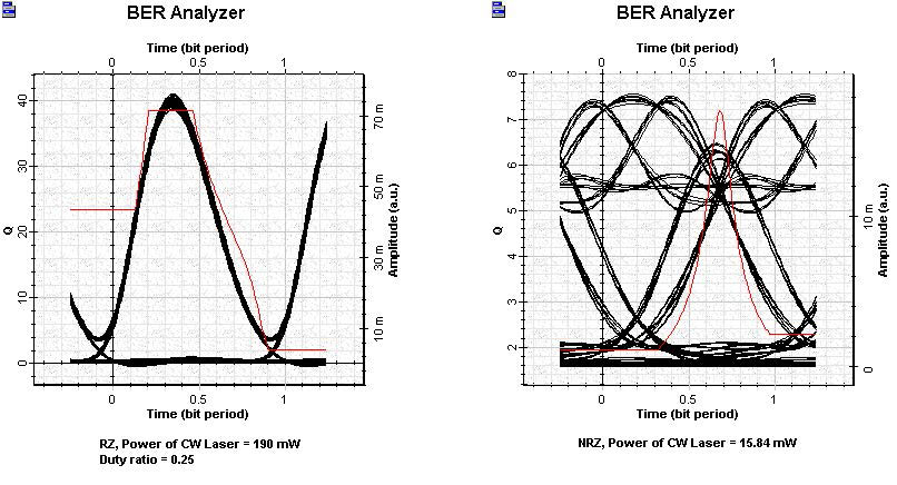
We will compare RZ and NRZ format transmission for a lossless case. Figure 2 shows the eye diagrams for both modulation formats after 100 km transmission at 10 Gb/s in lossless SMF.
Figure 2: Comparison of RZ and NRZ transmission
These results can be compared with results of Figure 1(a) and Figure 1(b) from [1]. A good agreement can be identified.
10 Gb/s transmission over SMF will now be analyzed, taking into account linear losses and ideal periodical amplification. Ideal periodical amplification is performed with the help of the OptiSystem Ideal EDFA component, which also takes ASE noise into account.
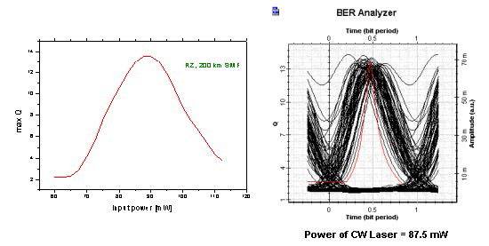
Figure 3 shows the results obtained with system applications 10 Gbps in SMF RZ.osd for 10 Gb/s RZ modulation format (duty ratio = 0.5):
• transmission over common distance from 200 km SMF (8 loops x 25 km)
• periodical amplification after each 25 km: gain = 5 dB
• noise figure = 6 dBm
The dependence of the max Q from the input power is shown in the graph. The BER Analyzer eye diagram represents the optimal point, which according to the graph, is input power ~ 87.5 mW.
Figure 3: 10 Gbps in SMF RZ results
A well-expressed maximum in the first graph can be seen.
Note: We have not performed any fitting of this curve.
At distances greater than 200 km, max Q becomes smaller than 6. Therefore, this is the maximum distance with good Q performance.
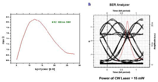
Figure 4 shows the results obtained with system applications 10 Gbps in SMF NRZ.osd for 10 Gb/s NRZ modulation format:
• transmission over common distance from 100 km SMF (4 loops x 25 km)
• periodical amplification after each 25 km: gain = 5 dB
• noise figure = 6 dBm
The dependence of the max Q from the input power is shown in the graph. The BER Analyzer eye diagram represents the optimal point, which according to the graph, is input power ~ 15 mW.
Figure 4: 10 Gbps in SMF NRZ results
A well-expressed maximum in the first graph can be seen.
Note: We have not performed any fitting of this curve.
At distances greater than 100 km, max Q becomes smaller than 6. Therefore, this is the maximum available distance with good Q performance.
References:
Comparing positions of the maximums of the two curves, we can clearly see the shift toward larger input powers for the RZ format.
The general conclusion from this lesson is that for amplifier spacing LA = 25 km at 10 Gb/s, the maximum transmission length for RZ (duty cycle = 0.5) ~ 200 km, whereas for NRZ ~ 100 km. The RZ is superior when compared to conventional NRZ – modulation format. This observation agrees well with numerical findings of [1] and [2].
[1] K. Ennser and K. Petermann, “Performance of RZ- Versus NRZ- Transmission on Standard
Single Mode Fibers”, IEEE Photonics Technology Letters, Vol. 8, pp. 443-445, 1996.
[2] M.I. Hayee and A.E. Willner, “NRZ Versus RZ in 10-40 Gb/s Dispersion – Managed WDM Transmission Systems”, IEEE Photonics Technology Letters, Vol. 11, pp. 991-993, 1999.


