Applications
- Photonic Crystal Fiber
- Optical Waveguide
- Laser Emission
- Optical Sensor
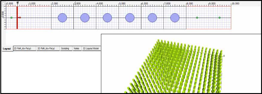
Photonic Crystal Layout
Benefits
- Reduce simulation size by using plane wave excitation and periodic boundary conditions
- Advanced modeling to achieve design goals quickly and efficiently, which significantly reduces product development cost
- Ability to take advantage of systems with multiple CPUs using multi-threading technology
- Built in PBG editor to define lattice relation
- Design creation in 2D and 3D
- PWE band solver
- Additional tool boxes allow the simulation input and output to be linked to other optical tools such as Zemax or Code V
- 64-bit capable
- Linux simulator available
Simulation Description
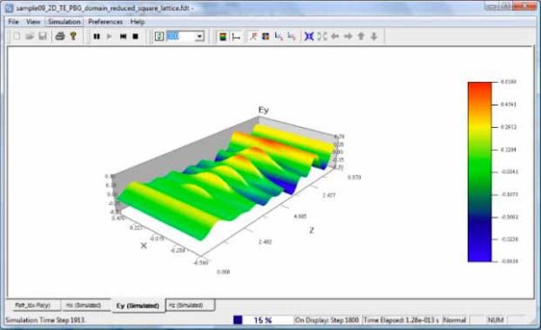
Most photonic crystals have a periodic lattice, which allows users to reduce the simulation size by using plane wave excitation and PBC boundary conditions. During simulation, the real-time propagation can be viewed in both 2D and 3D.
The diagram below shows the 3D wave propagation.
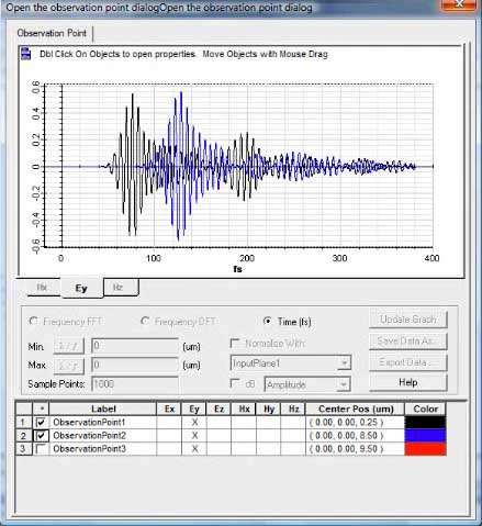
Observation points can be analyzed in real-time. Below is the reflected electric field in black and the transmitted field in blue.
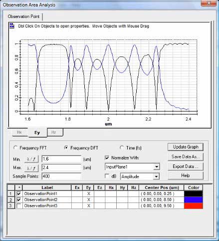
After simulation, transmission and reflection functions can be plotted.
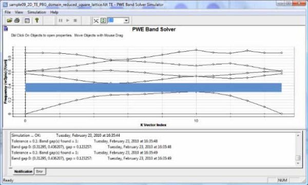
PWE Bandsolver
Allows users to identify band gaps that exist within the photonic crystal structure. The band solver works in either 1, 2, or 3-dimensions.
The diagram below is a graph populated with a set of eigen-frequencies provide a clear picture of the band diagram allowing users to identify band gaps.


