
- This topic has 8 replies, 2 voices, and was last updated 4 years, 10 months ago by
nik.paprocki.
-
AuthorPosts
-
-
July 25, 2021 at 12:46 pm #79705
 giusy samoneParticipant
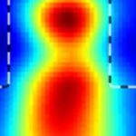
I am running the simulation of the model attached below, which has a geometry of several hundreds microns
This is the generated running script.
NumIterations = 1For x = 1 to NumIterations
ParamMgr.Simulate
WGMgr.Sleep( 50 )
NextAt the end of the running, I cannot visualize any E, and H.
I would really appreciate some help. -
August 6, 2021 at 7:17 pm #80257
 Scott NewmanModerator
Hello Giusy,
There appears to be a hiccup within the forum system and I cannot download your design file. Can you confirm what your mesh size is on the x and z? The copy I have has 0.1um which is far too large based on your source and material which would cause the simulation to be divergence hence the “No Valid Data” in your E and H.
Scott
-
August 6, 2021 at 7:17 pm #82861Scott NewmanModerator
Hello Giusy,
There appears to be a hiccup within the forum system and I cannot download your design file. Can you confirm what your mesh size is on the x and z? The copy I have has 0.1um which is far too large based on your source and material which would cause the simulation to be divergence hence the “No Valid Data” in your E and H.
Scott
-
August 8, 2021 at 7:05 am #80259giusy samoneParticipant
I tried 0.05 um for x and z, it took 6 hours for resolving the simulation but still there are not results.
-
August 8, 2021 at 7:05 am #82863giusy samoneParticipant
I tried 0.05 um for x and z, it took 6 hours for resolving the simulation but still there are not results.
-
August 9, 2021 at 2:21 pm #80261Scott NewmanModerator
Even that is still too course as you have a 0.46 um source and high index contrast. With any FDTD engine you need a bare minimum of 10 points per wavelength in order for the simulation to provide reliable results. So you are looking at something closer to 0.01 um just to start you analysis. You are attempting to model a very large (in terms of wavelengths) domain which is going to require significant computational resources and time to run a simulation.
-
August 9, 2021 at 2:21 pm #82865Scott NewmanModerator
Even that is still too course as you have a 0.46 um source and high index contrast. With any FDTD engine you need a bare minimum of 10 points per wavelength in order for the simulation to provide reliable results. So you are looking at something closer to 0.01 um just to start you analysis. You are attempting to model a very large (in terms of wavelengths) domain which is going to require significant computational resources and time to run a simulation.
-
August 11, 2021 at 5:21 am #80269giusy samoneParticipant
The computation becomes quite hard, and impossible to be handled by my pc.
Because the geometry is symmetric, can I just use 1/2 of the geometry.
Can I set the right boundary conditions for replacing the part I do not include into the geometrical model?
Is there any tutorial I can follow?
Thank you -
August 11, 2021 at 5:21 am #82873giusy samoneParticipant
The computation becomes quite hard, and impossible to be handled by my pc.
Because the geometry is symmetric, can I just use 1/2 of the geometry.
Can I set the right boundary conditions for replacing the part I do not include into the geometrical model?
Is there any tutorial I can follow?
Thank you -
August 16, 2021 at 3:35 pm #80273giusy samoneParticipant
Hi Scott,
based on this problem, it seems that the symmetry helped me to find some results.
Now I have a new issue, I was looking for the available tutorials but it seems that none can help me to extract the Reflected and transmitted signal versus the angle of incidence, like in a traditional SPR problem.
I would like to ask if you have any suggestions.
Thank you -
August 16, 2021 at 3:35 pm #82877giusy samoneParticipant
Hi Scott,
based on this problem, it seems that the symmetry helped me to find some results.
Now I have a new issue, I was looking for the available tutorials but it seems that none can help me to extract the Reflected and transmitted signal versus the angle of incidence, like in a traditional SPR problem.
I would like to ask if you have any suggestions.
Thank you -
August 16, 2021 at 5:32 pm #80275Scott NewmanModerator
You have two options for that.
- Set a parameter for the tilting angle and perform a parameter sweep on that parameter. From there you would obtain a series of simulations you could post process.
- Write a script that tilts the source within a for loop (effectively a parameter sweep) but from the script you could do much of your post processing.
Scott
-
August 16, 2021 at 5:32 pm #82879Scott NewmanModerator
You have two options for that.
- Set a parameter for the tilting angle and perform a parameter sweep on that parameter. From there you would obtain a series of simulations you could post process.
- Write a script that tilts the source within a for loop (effectively a parameter sweep) but from the script you could do much of your post processing.
Scott
-
August 18, 2021 at 5:03 am #80279giusy samoneParticipant
Hi Scott,
I am not sure to have understood the point. I have created the parameter tilting and assigned to it the values I would like to explore (see attached), but I have two more questions.
(1) how the model knows that this is the incident angle ? Indeed I got the four .fda files, but I do not think they refer to the different incident angle.
(2) I cannot open all the .fda together for the full analysis.
Besides, how can I get R versus angle and T versus angle?
This is common problem in plasmonic.
Thank you -
August 18, 2021 at 5:03 am #82883giusy samoneParticipant
Hi Scott,
I am not sure to have understood the point. I have created the parameter tilting and assigned to it the values I would like to explore (see attached), but I have two more questions.
(1) how the model knows that this is the incident angle ? Indeed I got the four .fda files, but I do not think they refer to the different incident angle.
(2) I cannot open all the .fda together for the full analysis.
Besides, how can I get R versus angle and T versus angle?
This is common problem in plasmonic.
Thank you -
August 18, 2021 at 12:09 pm #80283Scott NewmanModerator
You need to use a zip file to send compressed files.
- If you are using the “Tilting Angle” setting within the transverse settings of your input plane the injection algorithm uses this as the injection angle as defined from the normal of the input plane. Please note the angle is the angle between that normal and the input plane. You will need to make sure this matches your definition of “angle of incidence”.
- The specific graphs you are requesting you would need to create through the script or some external post processing.
Scott
-
August 18, 2021 at 12:09 pm #82887Scott NewmanModerator
You need to use a zip file to send compressed files.
- If you are using the “Tilting Angle” setting within the transverse settings of your input plane the injection algorithm uses this as the injection angle as defined from the normal of the input plane. Please note the angle is the angle between that normal and the input plane. You will need to make sure this matches your definition of “angle of incidence”.
- The specific graphs you are requesting you would need to create through the script or some external post processing.
Scott
-
-
AuthorPosts
- You must be logged in to reply to this topic.