(PVs) are arrays of cells containing a Solar photovoltaic material that converts solar radiation into direct current electricity. Materials presently used for photovoltaics include monocrystalline silicon, polycrystalline silicon, microcrystalline silicon, cadmium telluride, and copper indium selenide/sulfide.
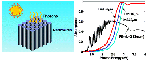
Silicon nanowire arrays are suggested to be promising candidates for photovoltaic cell research, due to the advantage in its short collection length and efficiency. FDTD simulations can help researchers and designers in this area to validate and optimize device dimensions, working bandwidth, and efficiency.
Using OptiFDTD, a simulation of the following published paper was accomplished with matching results:
Analysis of optical absorption in silicon nanowire arrays for photovoltaic applications.
Lu Hu, Gang Chen
Nano letters (2007)
Volume: 7, Issue: 11, Pages: 3249-52
* ISSN: 15306984
* DOI: 10.1021/nl071018b, PubMed ID: 17927257
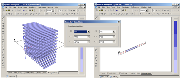
The simulation can be simplified based on the unit cell by Using the PBC boundary condition in transverse direction. When OptiFDTD simulates such an array with the normal plane wave incident, the simulation can be simplified based on one unit cell by using the PBC boundary condition in the transverse direction.
We model silicon using the advanced Drude-Lorentz simulation model included in OptiFDTD. Silicon material between 300nm and 800nm is very dispersive with the absorption factor. For dispersive materials, the Drude-Lorentz model contains both material intraband effects ( usually referred to as free-electron effect) and interband effects (usually referred as bound-electron effect) based on the measured refractive index data.
Users can drag and drop these sophisticated models from the material library into their project.
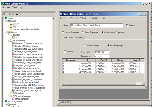
The Drude-Lorentz model in the frequency domain can be expressed as:
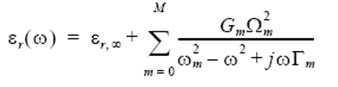
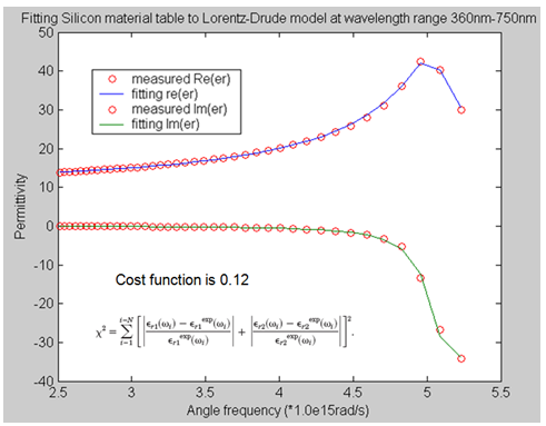
The following graph illustrated the permittivity of silicon from the measured data and the built in Drude-Lorentz model.
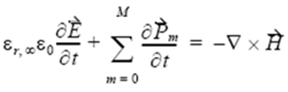
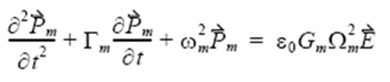
The Drude-Lorentz expression noted below is in the frequency domain, while FDTD is the time domain method. By employing the polarization philosophy and Fourier transform, the time domain Maxwell’s equation that contains the Drude-Lorentz effect can be built. The FDTD algorithm can be used to solve this equation:
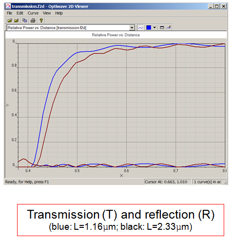
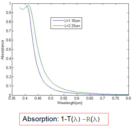
Simulation Results: