Fiber Loss
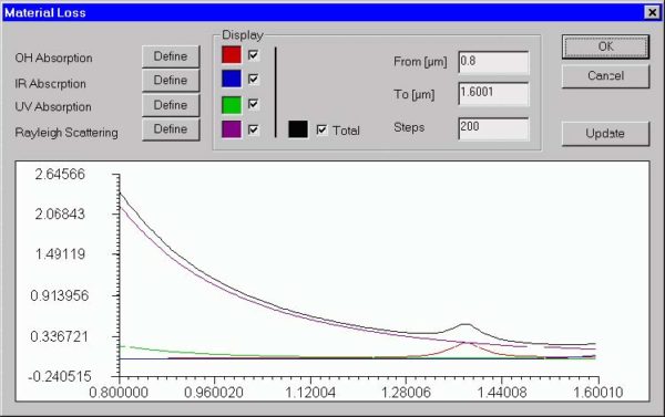
Material Loss dialog box The “Material Loss” dialog box allows you to define parameters for the material loss models and preview them on the attached display. The material loss includes the OH radicals, infrared, and ultraviolet absorption models, as well as the Rayleigh scattering model. To access this dialog box, do the following steps: Step…
Fiber Birefringence
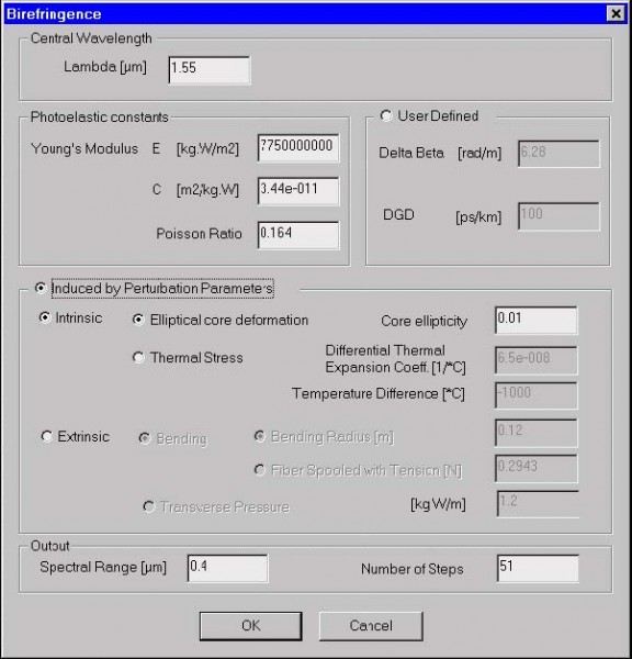
Birefringence dialog box The “Birefringence” dialog box allows you to define parameters of the fiber birefringence model. As described in the “Technical Background”, various mechanisms contribute to fiber birefringence. You can simply define birefringence values or follow one of the OptiFiber models. To access this dialog box, do one of the following steps: Step Action…
Polarization Mode Dispersion
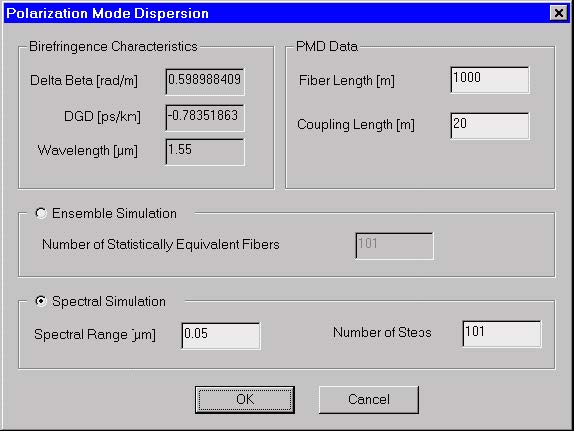
Polarization Mode Dispersion dialog box The “Polarization Mode Dispersion” dialog box allows you to define parameters of the PMD model as well as choose the PMD simulation method as the ensemble simulation or spectral simulation. Theoretically, both methods are equivalent. To access this dialog box, do the following steps: Step Action 1 Select “PMD” on…
Graph Related
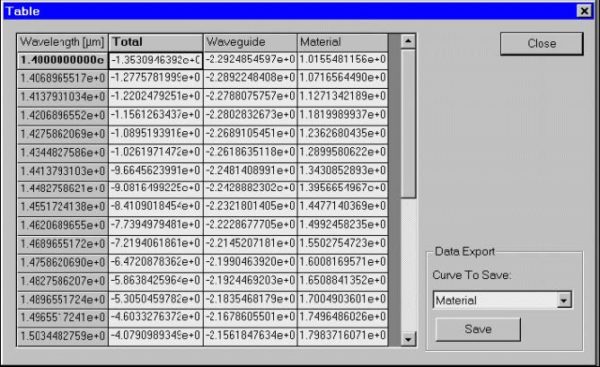
Table dialog box The “Table” dialog box allows you to inspect and export numerical data related to plots in the “Views” window. To access this dialog box, do the following steps: Step Action 1 Select one of the tabs in the output “Views” window 2 Select “Table” on the “Tools” menu The elements and controls…
Settings
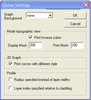
Global Settings dialog box The Global Settings dialog box can be used to change OptiFiber’s style of data entry and presentation according to user preference. The information in the Global Settings dialog box will be stored in the system registry. This means that the settings are remembered after OptiFiber is closed, and will remain in…
Profile
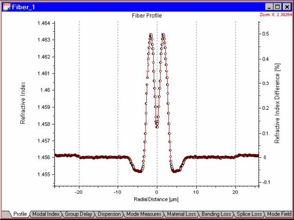
The “Profile” view shows you the fiber index profile as defined in the “Fiber Profile” dialog box. To access this view do one of the following steps: Step Action 1 Select the “Profile tab” in the “Views” window 2 Select “Views/Profile” on the “View” menu
Modal Index
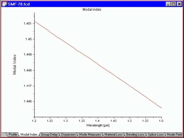
The “Modal Index” view shows you the effective refractive index of the selected propagation mode vs. the scan parameter. The default scan parameter is the wavelength. You can change the scan parameter in the “Properties of Fundamental Mode” dialog box or in the “Properties of Higher Order Modes” dialog box. To access this view do…
Group Delay
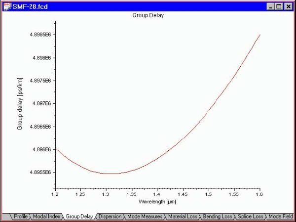
The “Group Delay” view shows you the propagation group delay for the selected fiber mode vs. the scan parameter. The default scan parameter is the wavelength. You can change the scan parameter in the “Properties of Fundamental Mode” dialog box or in the “Properties of Higher Order Modes” dialog box. To access this view do…
Dispersion
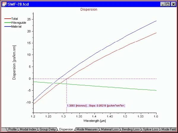
The “Dispersion” view shows you the material, waveguide, and total dispersion characteristics vs. the scan parameter. The default scan parameter is the wavelength. You can change the scan parameter in the “Properties of Fundamental Mode” dialog box or in the “Properties of Higher Order Modes” dialog box. To access this view do one of the…
Mode Measures
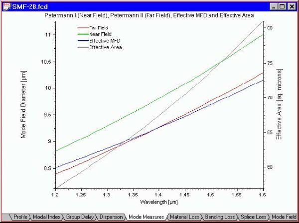
The “Mode Measures” view shows you the near-field, far-field and effective Mode Field Diameters (MFD) and the effective area of the fundamental mode vs. the scan parameter. The default scan parameter is the wavelength. You can change the scan parameter in the “Properties of Fundamental Mode” dialog box or in the “Properties of Higher Order…
Material Loss
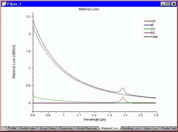
The “Material Loss” view shows you the material loss characteristics vs. wavelength. The loss is defined according to four models in the “Material Loss” dialog box, as well as the total material loss curve. To access this view do one of the following steps: Step Action 1 Select the “Material Loss” tab in the Views…
Bending Loss
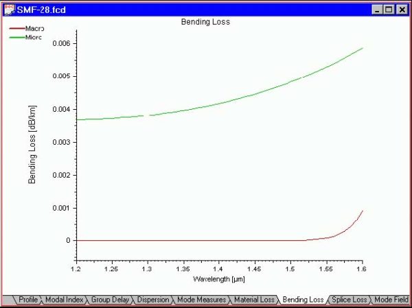
The “Bending” Loss view shows you the microbending and macrobending fiber loss vs. the scan parameter. The default scan parameter is the wavelength. You can change the scan parameter in the “Properties of Fundamental Mode” dialog box. To access this view do one of the following steps: Step Action 1 Select the “Bending Loss” tab…
Splice Loss
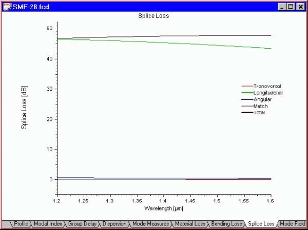
The “Splice Loss” view shows you the transversal, longitudinal, and angular misalignment loss, as well as the mode match and total splice loss vs. the scan parameter. The default scan parameter is the wavelength. You can change the scan parameter in the “Properties of Fundamental Mode” dialog box. To access this view do one of…
Birefringence
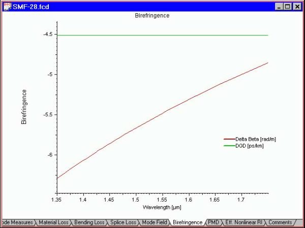
The “Birefringence” view shows you plots of: Delta Beta – Difference between the propagation constants of the two orthogonally polarized modes. DGD – Differential Group Delay (DGD) due to fiber birefringence vs. wavelength. To access this view do one of the following steps: Step Action 1 Select the “Birefringence” tab in the “Views” window 2…
PMD
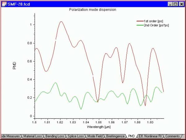
The “PMD” view shows you the Polarization Mode Dispersion (PMD) of the first and second orders vs. wavelength. To access this view do one of the following steps: Step Action 1 Select the “PMD” tab in the “Views” window 2 Select “Views/PMD” on the “View” menu

