In this tutorial we first describe the design flow involved in performing the co-simulation of an OptiSPICE circuit schematic with an OptiSystem optical design (via the OptiSPICE Netlist component). We then demonstrate the implementation of the OptiSPICE Netlist component for a two-level optical/electrical co-simulation (360 km NRZ transmitter to receiver link).
OptiSPICE is used to design the optical transmitter and receiver. First, the design of the laser driver for the transmitter and the photo-detector circuit for the receiver in OptiSPICE is reviewed and then integrated into OptiSystem for the NRZ transmission system.
The OptiSystem project related to this tutorial, TransmitterReceiverProject.osd, can be found in the “Samples” directory under “OptiSPICE cosimulation/System”. The associated OptiSPICE schematics, LaserDriver.osch and ReceiverProject.osch, can be found in the same location.
OptiSPICE and OptiSystem cosimulation design flow
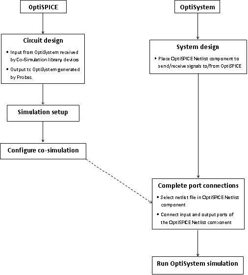
Figure 1 provides an overview of the design flow required to perform a successful OptiSPICE and OptiSystem co-simulation.
The purpose of the OptiSPICE Netlist component in OptiSystem is to call the OptiSPICE simulator to run the OptiSPICE netlist. The input and output ports of this component interact with the OptiSPICE design to send and receive optical and electrical signals. In OptiSPICE, the cosimulation library devices (electrical input – current source, electrical input – voltage source, and optical input) receive the electrical and/or optical signals generated by OptiSystem. Probes are then placed to generate the electrical and/or optical output for OptiSystem.
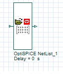
Initially, when retrieved from the Optiwave Software Tools Library of OptiSystem, the OptiSPICE NetList component in OptiSystem does not have any allocated ports (this is because the OptiSPICE design information is not yet configured (Figure 2))
Figure 1: Design flow diagram for an OptiSPICE/OptiSystem cosimulation
Figure 2: OptiSPICE Netlist component without ports
In order to create these ports, you first need to add the necessary OptiSystem Co-simulation input devices to the OptiSPICE schematic (obtained from the OptiSystem Co-simulation.clf library). These include:
- Electrical Input – Isource (current signal from OptiSystem)
- Electrical Input – Vsource (voltage signal from OptiSystem
- Optical Input (optical signal from OptiSystem)
For example in Figure 6 an Electrical Input – Isource component has been added (auto-labelled as “ElecInput_V1”) to the LaserDriver schematic to receive an NRZ Pulse Generator voltage input from OptiSystem. Similarly, in Figure 7, the “OptInput1” component has been added to the ReceiverProject schematic to receive the optical signal that has traversed the 360 km optical fiber link. Once all planned inputs have been created (multiple OptiSystem inputs are permitted) and probes have been placed to create the planned output ports to OptiSystem (for example the “M” probe at the output of “Laser1” in the LaserDriver schematic; the “Configure Co-simulation” function is selected from the OptiSystem tab. This action creates the OptiSPICE netlist as well as input/output port information.
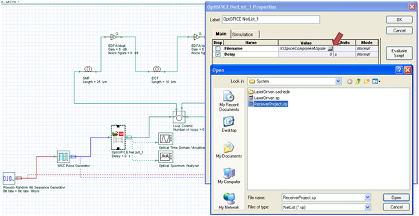
Following the creation of the OptiSPICE NetList, it is then possible to double-click on an OptiSPICE Netlist component on OptiSystem and to browse for the NetList filename that you wish to associate with this component (see Figure 3). Once the file name has been selected and OK is selected from the OptiSPICE NetList Properties dialog, the input and output ports are displayed, as shown in Figure 4.
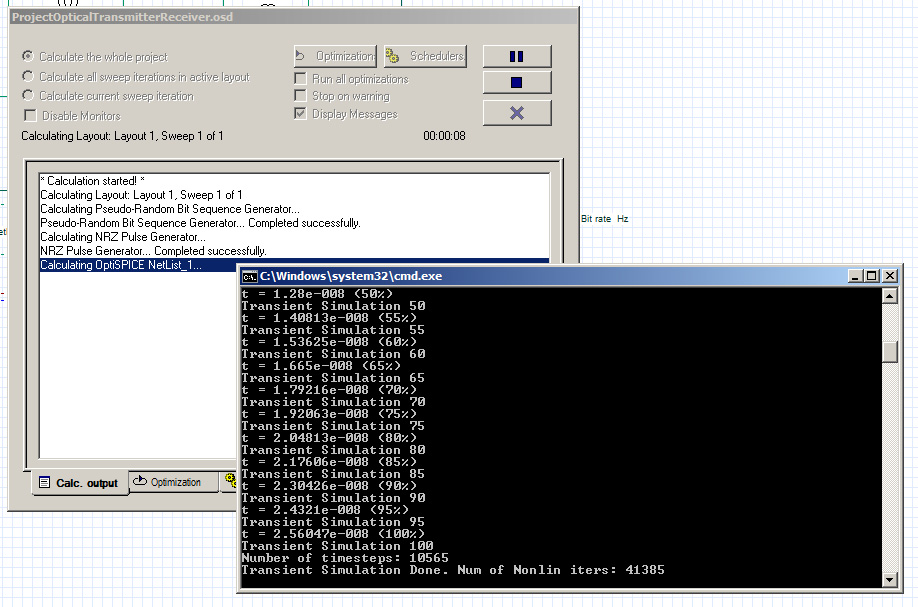
Once the ports are connected and your design is complete, run the simulation in OptiSystem (Calculate). During the simulation, a command line view of the OptiSPICE simulator will be launched each time the OptiSPICE simulation for each OptiSPICE netlist component is called (Figure 5)
Figure 3: Selection of the OptiSPICE Netlist file within the OptiSPICE Netlist component
Figure 4: Configured input and output ports
Figure 5: Launch of the OptiSPICE simulator during the OptiSystem calculation run
Transmitter and Receiver NRZ transmission link simulation
Laser Driver
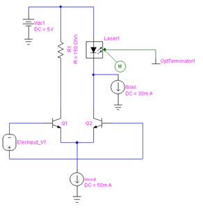
The laser driver schematic in OptiSpice is presented in Figure 6. The circuit is a differential current switch designed with two NPN transistors in a differential configuration. The electrical input is the bit pattern to modulate the laser light and a 5 volts DC power supply is used to bias the circuit. An optical terminator is connected to the output of the laser as the output port of the system.
Figure 6: Differential current switch laser driver
Photo-Detector Circuit
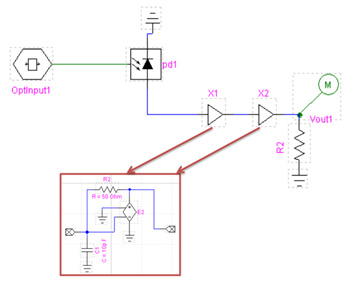
Figure 7 shows the circuit design of the receiver including the photo-detector. The photo-detector uses a PIN model and X1 and X2 are two Transimpedance amplifiers.
Figure 7: Electrical receiver circuit design
NRZ optical transmission simulation with OptiSpice Netlist
To integrate these two designs in OptiSystem, we need to create the Netlist for each schematic. This can be done by clicking on the “OptiSystem” tab within the OptiSPICE Schematics Editor and selecting “Configure Co-simulation”. OptiSPICE then generates the “filename.sp” file in the same directory. For example if the LaserDriver.osch schematic is opened in OptiSPICE, the LaserDriver.sp Netlist file will be generated within the same directory.
Figure 8 demonstrates the simulation setup for the NRZ optical transmission. The transmitter is the laser driver designed in OptiSpice and transferred to OptiSystem using the OptiSPICE Netlist component located in the “Optiwave Software Tools” library. Drag the component inside the layout and double-click on it. As it can be seen in Figure 9, choose the <*.sp> file from the directory.
We have used the loop configuration for the signal propagation. Two spools of SMF with a length of 25 km, 10 km of DCF and three EDFAs are used in the loop. In this example, the signal propagates inside the loop for 6 times for 360 km of propagation.
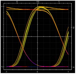
The receiver is the photo-detector circuit designed in OptiSPICE. The same procedure is used to load the design to OptiSystem. A low-pass Bessel filter is used to remove RF noise and a BER analyzer to see the eye diagram and measure the BER. As it can be seen, the eye is open and the transmission is error-free (see Figure 10).
Figure 8: 360 km of NRZ transmission using OptiSpice laser driver and receiver circuits
Figure 9: Configuration of OptiSpice Netlist Component
Figure 10: Eye diagram of NRZ signal transmission after 360 km


