Laser Noise and Linewidth
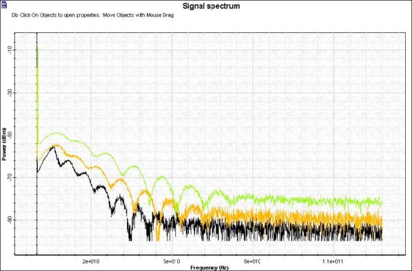
Laser Intensity Noise.osd (see Figure 1) shows the laser spectral in CW operation at several power levels. Figure 1: Laser Intensity Noise The laser exhibits fluctuations in its intensity, phase, and frequency, even when the laser is biased at a constant current with negligible current fluctuations (see Figure 2). Figure 2: Laser Noise
Vertical-Cavity Surface-Emitting Laser – VCSEL Validation

The purpose of this lesson is to compare the simulation results of the VCSEL laser component with the published articles [1] and [2]. The first part of the lesson will compare the LI and IV curves of the component for different input parameters with the experiments presented in [2]. The second part of the lesson…
Using the Laser Measured Component

The purpose of this lesson is to demonstrate how to obtain the laser physical parameters from measurements. Case 1: Setting the measured values Z, Y, P1 and Ith to obtain the correspondent physical parameters: Using the measured values obtained in [1], set up the measured tab in the laser component: P1 = 1.36 mW @…
Effects of Group Velocity Dispersion (GVD) on Gaussian Pulse Propagation

To demonstrate the influence of the group (GVD) velocity dispersion on pulse propagation in optical fibers in “linear” regime. The basic effects related to GVD are: GVD induced pulse broadening GVD induced pulse chirping Pulse compression The equation, which describes the effect of GVD on optical pulse propagation neglecting the losses and nonlinearities, is [1]:…
Effects of PMD on Pulse Propagation

Polarization mode dispersion (PMD) can cause serious problems in high bit-rate transmissions. In this lesson, the PMD emulator component is used to demonstrate the distortions in the transmitted signal, caused by first and second order PMD effects. The system showed in Figure 1 is utilized in the simulations. Figure 1: PMD system layout The system…
Effects of Cross Phase Modulation (XPM) and Four-Wave Mixing (FWM)
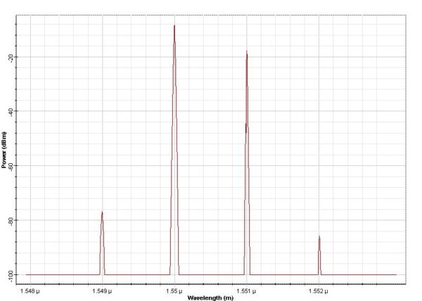
The purpose of this lesson is to give an idea about the effects associated with cross-phase modulation (XPM) and four-wave mixing (FWM) accompanying the propagation of optical signals at different carrier frequencies in a nonlinear dispersive fiber [1]. At first, we create the layout shown in Figure 1. The Numeric tab of the Nonlinear Dispersive…
Combined Effects of GVD and SPM on Gaussian Pulse Propagation
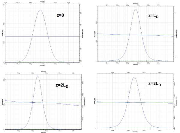
This lesson demonstrates that the effects of SPM and anomalous GVD on the pulse propagation are counteracting. As already discussed, (see the “Group velocity dispersion” in the Tutorials), the effect of GVD on the pulse propagation depends on whether or not the pulse is chirped. With the proper relation between the initial chirp and the…
Combined Effects of GVD and SPM on Modulational Instability

This lesson demonstrates that the propagation of a CW beam inside an optical fiber is inherently unstable due to the interplay between the anomalous GVD and SPM. The layout and the parameters are shown in Figure 1. Figure 1: Layout and parameters The CW Laser is used as a pump source (Figure 2). Its “Linewidth”…
PMD-Induced Broadening of Ultra-Short Pulses

This lesson demonstrates the broadening of a “very short” (Dirac δ-shaped) pulse caused by polarization mode dispersion (PMD). It also shows that the probability distribution function of the differential group delays between the principal states of polarization generated by the component agrees well with the Maxwellian one. The “coarse step” method [4], [5] with fiber…
Validation of FWM Effect
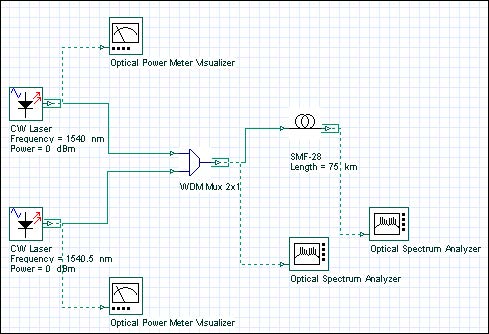
This tutorial demonstrates the validity of the FWM algorithm, as well as providing the user with some useful designing tips for optimizing simulation time and accuracy. The layout in was used to obtain results, and can be found in the sample file FWM Validation.osd Figure 1: FWM project layout In the two CW Lasers, the…
Stimulated Raman Scattering
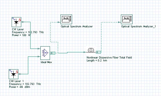
This lesson demonstrates the light amplification caused by the stimulated Raman scattering effect. The layout and its global parameters are shown in Figure 1. Figure 1: Layout and global parameters Figure 2 shows the setup for the optical fiber component. Figure 2: Setup parameters The spectrum of the input signal consists of a strong pump…
Stimulated Raman Scattering—Separated Channels

The purpose of this lesson is to demonstrate light amplification resulting from the stimulated Raman scattering effect. The layout with its global parameters is shown in Figure 1 Figure 1: Layout and global parameters The input spectrum (Figure 2) consists of a strong (pump) wave at 193 THz (100W) and four weak (probe) waves at…
SPM-Induced Spectral Broadening

This lesson demonstrates the basic effects of self-phase modulation (SPM) on pulse propagation. These include: Pulse chirping Pulse spectral broadening The effects SPM of are described by [1]: where E(z, t) is the electric field envelope, and the parameter y is given by: In Equation 2, ω0 is the carrier (or reference) frequency, n2 is…
XPM-Induced Asymmetric Spectral Broadening
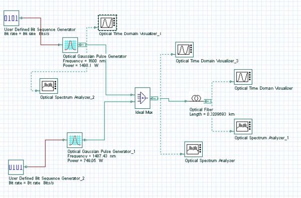
The purpose of this lesson is to demonstrate the asymmetric spectral broadening caused by XPM. The layout along with the global parameters are shown in Figure 1. Figure 1: Layout and global parameters The input consists of two superimposed Gaussian pulses [1] (Figure 2). Figure 2: Superimposed Gaussian pulses The carrier wavelengths of the pulses…
Kerr Shutter
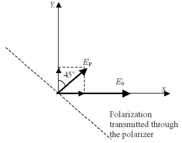
The purpose of this lesson is to demonstrate that the Kerr effect in optical fibers can be used to produce ultra-fast all-optical switch (shutter).

