Parameter Sweep Simulation Introduction

There are two ways to perform the parameter sweep simulation with OptiFDTD: • Simulation Using Script. This method asks the user to edit the VBscript code to sweep the layout parameters. The user can use the internal VB function to access the power spectrum. • Simulation Using automated Sweep. With this method, OptiFDTD provides a…
VB Script Function for Observation Line
10 PowerAtCenterWavelength() Purpose: Calculates power at the Center Wavelength. The Center Wavelength value is specified at the primary (key) Input Plane. All types of 2D (CW, GMCW) simulations support this function. 11 PowerAtWavelength( double dWavelength ) Arguments: dWavelength– specifies a wavelength value for which the calculations should be performed. Wavelength value must be greater than zero. Purpose:…
Layout Creation Steps

Step Action 1 Open OptiFDTD Waveguide layout Designer. From the Start menu, select Programs ->Optiwave Software ->OptiFDTD->Waveguide Layout Designer. OptiFDTD_Designer. 2 Create a new project. From the OptiFDTD_Designer File menu, select New. The Initial Properties dialog box appears. 3 Define the material(s) and waveguide profile(s) that will be used in the project. Click the Profiles…
Parameter Sweep Setting

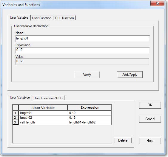
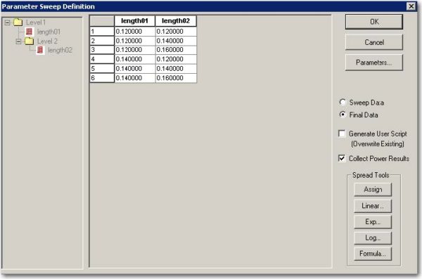
In this sample, we want to sweep two parameters: length01 and length02. Variable lengh01 will have two iterations with corresponding values of 0.12µm, 0.14 µm. Variable length02 will have three iterations with corresponding values of 0.12 µm, 0.14µm, 0.16µm. We will set two sweep levels: level one will scan parameter length01 and level two will scan parameter length02…
Incident Wave Source Excitation – Total/Reflected Field Formulation

Step Action 1 From the Draw menu, select Vertical Input Plane. (Or select it from the shortcut toolbar) 2 To insert the input plane, click in the layout window where you want it placed. The input plane appears in the layout. 3 To edit the input plane, double-click on the input plane in the layout.…
Observation Line
Step Action 1 From the Draw menu, select Observation Vertical Line. 2 Place the Observation Line in the desired position in the layout. 3 Double-click the observation line. The Observation Properties — Vertical Line dialog box appears. 4 On the General tab: In Center, Offset, type/select the following: Horizontal: 0.5 Vertical: 0.0 X Length Offset: 3.0…
Simulation Parameters
Step Action 1 From the Simulation menu, select Simulate 2D Using 64-bit Simulator. The Simulation Parameters dialog box appears. 2 Type/select the following information: Polarization: TM Unselect Auto for mesh Mesh Delta X [µm]: 0.02 Mesh Delta Y [µm]: 0.02 3 Click the Advanced button to check the boundary condition settings. Default parameter is for most…
Parameter Sweep Simulation
• Select the Simulate 2D Using 64-bit Simulator under simulation menu. • Click Run to start the simulation. The progress window appears. It displays status of the simulations and the iteration number. • User can also observe the intermediate simulation results by clicking the Simulation menu and set the snapshot objects. The time domain response…
Power Sweep Analysis

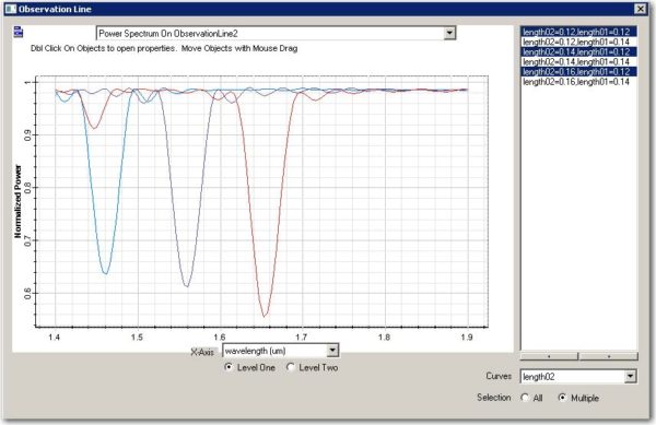
• Open each fda file to observe the field pattern and power spectrum in the observation line for the corresponding scanned parameter. The scanned parameter value will be listed in the analyzer. • The final fda file will collect the center wavelength power values and power spectrums in the observation line for all the simulated iteration. Step Action…
64-bit 3D Simulator Introduction
The workflow required to perform simulations with 64-bit 3D Simulator is almost the same as for the “regular” 32-bit simulator(s): Step Action 1 Create a New Layout a. Define the material and waveguide in profile designer b. Set up the initial simulation domain c. Draw the waveguide 2 Define simulation parameters 3 Define input wave…
New Layout
The following lesson uses straight channel waveguide as an example. Note: • The corresponding project file can be found in the Sample file folder, Sample43_64bit_3D_Simulations_Getting_Started.fdt. • If you already familiar with layout creation, please open the example project and go to the step “Perform the 64Bit-FDTD FDTD Simulation” • Please see other tutorial lessons to…
Heating Absorption Simulation Introduction

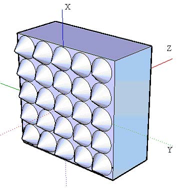
Metallic and lossy materials in solar cells or other semiconductor devices in general absorb part of the light wave energy, converting it to heat. This lesson demonstrates the heating absorption simulation in OptiFDTD. The layout we will simulate is shown in Figure 1, the corresponding project file (Sample44_3D_Heating_Absorption_64bit.fdt) can be found under the Sample folder of your software…
Input Wave
The Input Wave signal is defined within the Input Plane. To insert the Input Plane and set the excitation wave, follow the steps below: Step Action 1 From the Draw menu, select Vertical Input Plane, or select Vertical Input Plane shortcut toolbar (The Vertical Input Plane is in the x-y plane for 3D.) 2 Click in…
Simulation Parameters

Step Action 1 From the Simulation menu, select Simulate 3D Using 64-bit Simulator. The 3D Simulation Parameters dialog box. 3D simulation parameters dialog box ( Figure 3) Figure 3: 3D Simulation parameters dialog box 2 Uncheck Auto in the mesh parameters region, type the following values for the mesh size: Mesh Delta X (mm): 0.025 Mesh…
References
[1] Joannopoulos, J.D., Meade, R.D., Winn, J.N., “Photonic Crystals, Molding the flow of light”, Princeton University Press 1995

