Plane Wave Simulation Introduction
OptiFDTD provides two special boundary conditions—perfect electrical conductor (PEC) boundary and perfect magnetic conductor (PMC) boundary. The two boundary conditions can works with Anisotropic PML together to realize the plane wave simulation. For more details of these boundary conditions, please see the Technical Background. This lesson presents a 2D plane wave simulations and 3D plane…
2D-TE Plane Wave in Unique Material
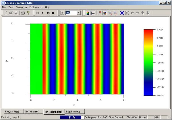
Creating a layout Step Action 1 Open the Waveguide Layout Designer. 2 To create a new project, select File > New. The Initial Properties dialog box appears. 3 Click Profiles and Materials. The Profile Designer window appears. 4 Under the Materials folder, right-click the Dielectric folder and select New. A new Dielectric material dialog box…
3D-Y-Direction Polarized Plane Wave in Unique Material
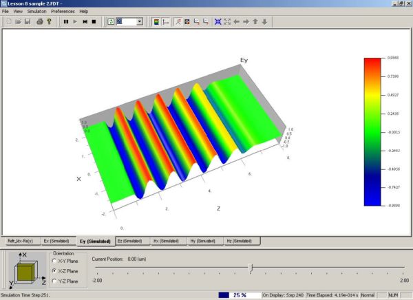
Using the same layout created in 2D-TE plane wave in unique material, create another file with the same layout by selecting File > Save As and using a different file name. Step Action 1 From the Edit menu, select Wafer Properties. The Wafer Properties dialog box appears. 2 Click the 3D Wafer Properties tab and…
FDTD Band Solver Introduction
FDTD Band Solver in OptiFDTD is a supplementary tool for the Photonic Crystal (PhC) and Photonic Band Gap (PBG) structure. Currently it employs the FDTD method and generates what is called the Band Diagram. For the transmission and reflection analysis for PhC and PBG, it is still suggested to use the conventional FDTD method demonstrated…
Photonic Crystal Structure
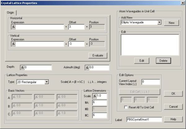
Step Action 1 Open the OptiFDTD Waveguide Layout Designer. 2 To create a new project, select File > New. The Initial Properties dialog box appears. 3 Click Profiles and Materials. The Profile Designer window appears. 4 Under the Materials folder, right-click the Dielectric folder and select New. A new Dielectric material dialog box appears. 5…
Band Solver Parameters
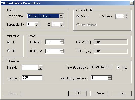
When you open the 2D Band Solver Parameters dialog box (from the layout designer Simulation menu), OptiFDTD automatically checks to see if the lattice structure exists in the layout. Available lattice structures are listed under Domain, in the Lattice Name drop-down list. Currently only 2D square lattice and 2D hexagonal lattice are supported. The FDTD…
Lorentz-Drude Model for Metal and Surface Plasma Introduction
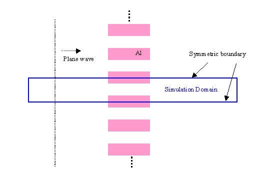
OptiFDTD versions 2 through 4 provided a Drude model and a separate Lorentz model for metal, plasma and dispersive material simulation. The two models work only for 2-dimensional (2D) layouts. Based on feedback from our customers, OptiFDTD 5.0 introduced a combined model called the Lorentz-Drude model. This model can handle both the Drude and Lorentz dispersive…
Enhancement
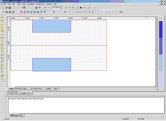
In the above parameter set up, if we only set one term, and set resonant frequency as zero, we will simulate a Drude model material 7 Click “Store” to save the defined material. The “Lorentz_Drude_Al” will be listed in the FDTD-Dielectric folder of the Waveguide Profile Designer 8 In the directory under “OptiFDTD_Designer1” Profile folder, right-click…
Discussion
This lesson utilizes 2D layout to demonstrate usage of Lorentz-Drude materials in OptiFDTD simulations. Materials in this layout can be switched to perfect conductor or other metals to observe their interaction with the optical field 3D simulation for Lorentz-Drude material has the same concept as 2D simulation. However, if Lorentz-Drude material in 3D layout touches the…
Refractive Index Distribution
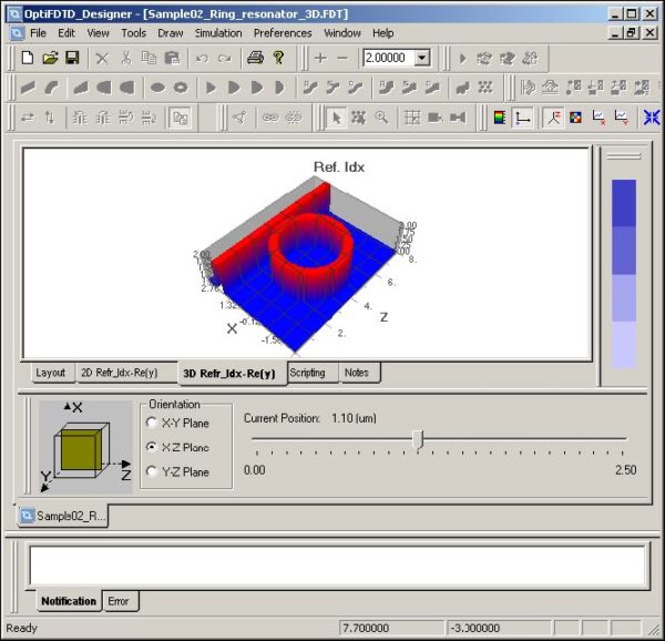
OptiFDTD provides a refractive index viewer to observe the refractive index distribution on any plane in three orientations. To observe the refractive index distribution, perform the following procedure. Observing the Refractive Index Distribution Step Action 1 Click the 3D Ref. Index tab at the bottom of the layout window. The 3D Refractive Index window opens.…
Analyzing 2D Photonic Crystals Introduction
The tutorial demonstrates analysis of 2D photonic crystal using PWE Band solver. First we create a lattice model of dielectric cylinders (permittivity=8.9) suspended in air. We then proceed with a simple simulation on a predefined k-vector path and result analysis. Finally we discuss the meaning of the Domain Origin in the PWE dialog box. Step …
References
[1] Joannopoulos, J.D., Meade, R.D., Winn, J.N., “Photonic Crystals, Molding the flow of light”, Princeton University Press 1995
2D Rectangular Lattice of Dielectric Cylinders
Note: For the details on how a lattice can be created, please refer to Lesson 3— Photonic crystal and photonic band gap simulation and Lesson 9—FDTD Band Solver. For the details on how material and waveguide profile can be created, please refer to lesson 1 to lesson 9 To define the variable, please input the…
PWE Band Solver Parameters
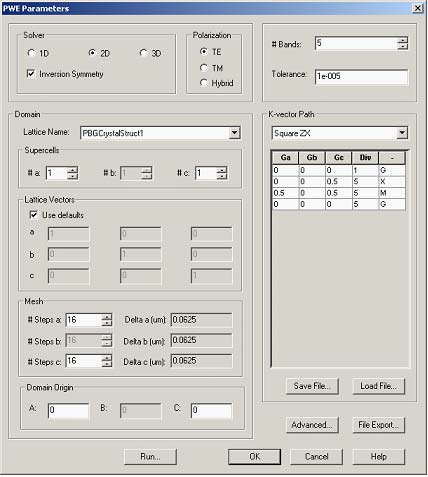
Open PWE Parameters dialog box (Simulation->PWE Band Solver Parameters…). By default the PWE solver should be set to 2D Solver, TE polarization, no inversion symmetry. The Lattice vectors should use defaults, i.e. the mesh (#Steps a, #Steps c) should be set to 16×16. Also make sure the Domain origin is set to (0,0,0). Set number…
Simulation Results
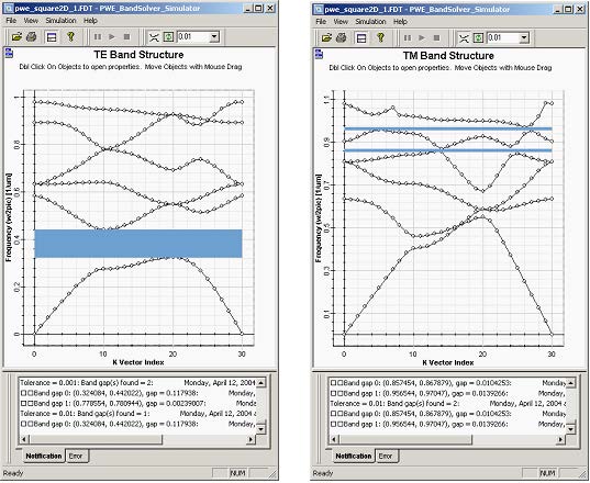
When finished with editing band solver parameters click Run… to start the simulations. A simulation windows will be launched and simulation starts. You will be notified in the Notification tab window at the bottom about progress of the simulations. The engine first reports on the permittivity averaging process, then on the progress of calculations for individual…

