Material Dispersion

Step 1 In this step, you will create a new project. Choose the Single Fiber Module, and define fiber parameters. To define fiber parameters 1 On the Toolbar, click the New button. 2 In the New dialog box, click Single Fiber. 3 In the Project Window, click the Fiber/Waveguides Parameters button. 4 In the Single…
Lesson 2 – Sensors

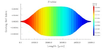
In this lesson, you will use the Fiber Bragg Grating example from Lesson 1. Have a look at the Profile graph. Step 1 In this step, you will learn to define Sensor characteristics. To define Sensor characteristics 1 Select Grating from the Parameters menu, or simply select the Grating icon on the left. 2 In…
Lesson 1 – Fiber Bragg Grating

In the first lesson, you will learn how to design a Fiber Bragg Grating with chirp and apodization. Such a grating finds application in fiber dispersion compensation. S.1 The first thing you will do is to open a new project. Then, you will choose one of the five available modules to work with: Single Fiber,…
Integrated & Fiber Optical Gratings
An integrated or fiber optic grating is a periodic modulation of the refractive index in a waveguide or on the surface of a waveguide. It can be fabricated by using either twobeam interferometry or near-field holography through an optical phase mask. Waveguide gratings play an important role in WDM systems since they can be used for controlling, combining, and…
Coupled Mode Theory
Coupled Mode Theory is a method to analyze the light propagation in perturbed or weakly coupled waveguides. The basic idea of the Coupled Mode Theory method is that the modes of the unperturbed or uncoupled structures are defined and solved first. Then, a linear combination of these modes is used as a trial solution to…
Index Profile of Fibers or Slab Waveguides

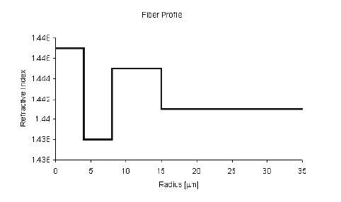
The radial distribution of the fiber refractive index is called the index profile. In the case of a slab waveguide, the transverse refractive index is called the index profile. The index profile determines guiding properties of the fiber or slab waveguide. In general, the core region has a higher index than the cladding region. However,…
Waveguide Modes

In a waveguide, light propagates in the form of modes. OptiGrating 4.2 uses LP Fiber modes, Vector Fiber modes, and Slab Waveguide modes. LP Fiber Modes The designation of Linearly Polarized (LP) Fiber modes is based on the assumption of weak guidance. Weakly guiding fibers have a small difference between core and cladding refractive index. The LP…
Material and Waveguide Dispersion

Material refractive index varies with wavelength and therefore causes the group velocity to vary; it is classified as material dispersion. The wavelength dependence of refractive index can be expressed by Sellmeier’s equation. Waveguide dispersion is the result of wavelength-dependence of the propagation constant of the optical waveguide. It is important in single-mode waveguides. The larger…
Complex Index Profile

In OptiGrating 4.2, the index profile of the fiber or slab waveguide can be complex. The imaginary part of the modal effective index can be calculated by the perturbation method based on the coupled mode theory as: where N is the number of layers of the waveguide index profile, Ki is the imaginary part of…
Photosensitivity Profile of the Fiber and the Slab Waveguide

It is well known that a germanium-doped silica fiber exhibits photosensitivity, i.e., a permanent change in the refractive index of the core when it is exposed to light from an appropriate laser. High photosensitivity can be achieved by increasing concentration of germanium, codoping suitable elements which has enhanced photosensitivity, and high pressure hydrogen loading etc.…
Grating Device Modeling

Single Grating Formula A grating can be represented by the formula that combines a grating shape function, an average index modulation function, a period chirp function, and an apodization function: where n0 – waveguide refractive index Δn – index modulation amplitude θ -grating tilt angle ƒ[Λ(z)/cosθ, z] – shape function Δn0(z) – average index modulation function Λ(z) –…
Coupled Mode Equations

Assume the electric field is a linear combination of the ideal modes (with no grating perturbation), such that where ai(+) and ai(-) are the slowly varying amplitudes of ith mode traveling in the +z and –z directions. βi and is the propagation constant and modal field of the ith mode. The above electric field is used…
Transfer Matrix Method
If the device has more than one grating plus phase shifts, the coupled mode equations can be solved by the Transfer Matrix Method. This method can also be used very effectively in the analysis of almost-periodic gratings. The general idea of TMM is that the grating structure is divided into a number of uniform grating…
Grating Pulse Response
The Coupled Mode Equations are derived in the context of a monochromatic frequency CW light source for linear propagation. The spectrum of the input pulse can be obtained by taking a Fourier transform of the input time-dependent waveform. The response to the input pulse can be calculated by considering each spectral component separately and adding…
Fiber Grating Sensor

Temperature and strain change the grating period as well as the grating refractive index. Consequently, the response of the grating device is changed when temperature and strain distributions change. Strain-optic effect of fiber Bragg grating The changes of optical indicatrix caused by strain are: where, ε1 = ε2 = –vε, ε3 = ε, ε4 =…

