Tracking

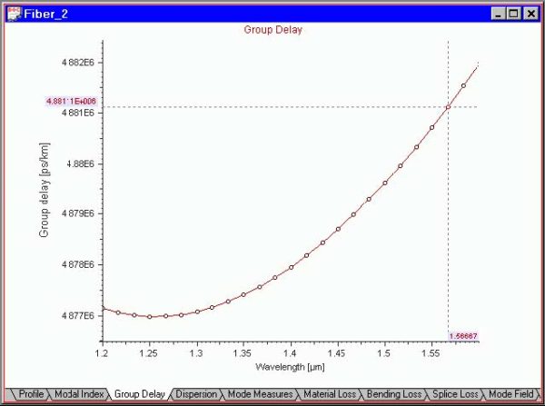
The “Tracking” tool shows the XY coordinates of a point of a curve. Do the following steps: Step Action 1 Select the “Group Delay” tab in the Views window. 2 Select “Tracking” from the “Graph Tools” floating menu or the “Graph Tools” toolbar. 3 With the left mouse button, click-and-drag to track the coordinates. 4…
Legend
The “Legend” tool shows the short descriptions of the curves in multi-curve graphs. Its use is identical to that of the other graph tools. The legend can be dragged, so the user can position it anywhere on the “Views” tab.
Refractive Index of Fibers

Host materials Optical telecommunication-grade fibers are made usually from silica glasses. The high purity glass is called the host material or substrate. Its bulk refractive index usually defines the refractive index of the fiber cladding. Adding dopant materials to the host material forms the fiber core. Dopant materials To change the refractive index of optical…
Fiber Propagation Modes
Scalar fiber modes The designation of Linearly Polarized (LP) Fiber modes is based on the assumption of weak guidance. Weakly guiding fibers have a small difference between core and cladding refractive index. Two numbers designate the LP (m, n) modes: m – azimuthal number n – orbital number where m = 0, 1, 2, ……
Group Delay and Dispersion Definitions

Material dispersion of the bulk glasses If the refractive index of the fiber material varies with wavelength, thus causing the group velocity to vary, it is classified as material dispersion. The group delay Tg is given by the product of the propagation distance z by the first frequency-derivative of the propagation constant: where n is…
Mode Field Diameter and Mode Area Definitions

Mode field diameter and area importance The Mode Field Diameter (MFD) is an important parameter related to the optical field distribution in the fiber. It has been shown that MFD provides useful information about the cabling performances, such as possible joint, macrobending, and microbending losses. The effective area of the fibers has a direct relation…
Cutoff Wavelengths
The cutoff wavelength for any mode is defined as the maximum wavelength at which that mode will propagate. The cutoff wavelength λc of LP11 is an important specification for a single-mode fiber. The operation wavelength must be greater than the cutoff wavelength of LP11 to operate the fiber in a single mode regime. λc can be determined analytically…
Fiber Loss Models

Fiber propagation loss definition The total fiber loss can be divided into material losses and fiber induced losses. Material losses include Rayleigh scattering, ultraviolet (UV), infrared (IR) absorption, and hydroxyl (OH) absorption losses. Material losses are the limiting losses in fibers. Fiber loss is defined as the ratio of the optical output power Pout from…
Fiber Birefringence Models

Fiber birefringence definition The birefringence is defined by the difference between the propagation constants of the polarization Eigenmodes, that is: The Differential Group Delay (DGD) per unit length is defined by: Intrinsic perturbations birefringence Intrinsic perturbations are accidentally introduced in the manufacturing process and are permanent feature of the fiber. These include a noncircular core…
Polarization Mode Dispersion Models
Polarization mode dispersion In ideal single-mode fibers, propagation constants of the two polarization Eigenmodes are degenerate. In real telecommunications fibers, perturbations act on the fiber in a way that it induces a birefringence, which splits this degeneracy. Consequently, when a pulse is launched in a fiber, it gives rise to a differential group delay between…
Technical References
[1] M. J. Adams, “An introduction to Optical Waveguides,” John Wiley & Sons, 1981. [2] M. Artiglia, “Mode field Diameter measurements in single-mode optical fibers,” J. Lightwave Tech. Vol. 7, no. 8, pp. 11391152, 1989. [3] F. Bruyère, “Effets de Polarisation dans les Systèmes à Amplification Optique de Longue Distance”, Ph.D dissertation, Univ. of Paris XI Orsay,…
Dispersion Flattened Fiber

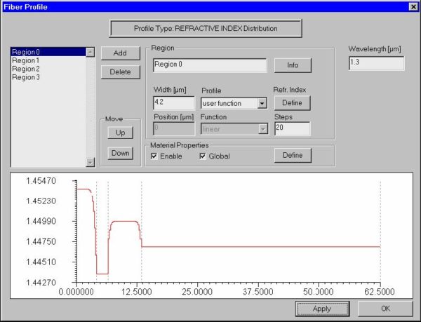
In this example, we will simulate a dispersion flattened fiber. We will also demonstrate the use of the internal scripting language of OptiFiber for defining profiles. You can find this example as the DFF.fcd file in the Samples directory. Defining fiber profile To define a fiber profile, follow these steps: Step Action 1 From the…
File
New command The “New” command opens a new OptiFiber file with empty “Views” window, except the “Material Loss” view. Fiber parameters have default values. OptiFiber creates a default name for the newly opened file. This command can be accessed from: File menu Standard toolbar Open command The “Open” command opens an existing OptiFiber file. The…
View
Status Bar The “Status Bar” command toggles the display of the status bar at the bottom of the OptiFiber workspace window. This command can be accessed from: View menu Navigator command The “Navigator” command toggles the display of the “Navigator” pane in the OptiFiber workspace window. This command can be accessed from: View menu Toolbars…
Fiber
Profile command The “Fiber” command opens the “Fiber Profile” dialog box, where you can design the refractive index profile of the fiber and have access to the dispersion properties of the fiber materials. This command can be accessed from: Fiber menu Fiber Profile icon on the Navigator pane:

