Lorentz-Drude Model in Time Domain
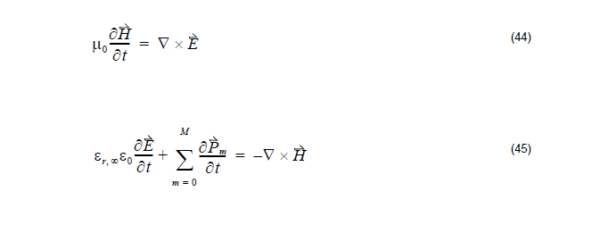
The Lorentz-Drude model in (43) is in the frequency domain. However, FDTD is a time domain method and therefore would be suitable for broadband simulations. We need to transform (43) to time domain so that FDTD can handle the fullwave-analysis for the Lorentz-Drude material. This transformation to time domain is accomplished by using the Polarization…
Run Simulation and View Results
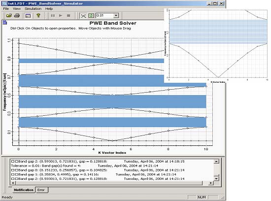
When finished with editing band solver parameters click Run… to start the simulations. A simulation window will be launched and simulation starts. You will be notified in the output window at the bottom (Notification tab) about progress of the simulations. After the simulation is finished the graph is populated with set of eigenfrequencies of individual k-vectors.…
Installing OptiFDTD
Before installing OptiFDTD, ensure the system requirements described below are available. Hardware and software requirements OptiFDTD requires the following minimum system configuration: Microsoft Windows XP/Vista/7, 32-bit or 64-bit, note: 64-bit OS is required to run 64-bit simulators Personal computer with Pentium 4 or higher processor 1.2 GHz (or higher). Multicore CPU is required for increased performance…
FDTD Basics
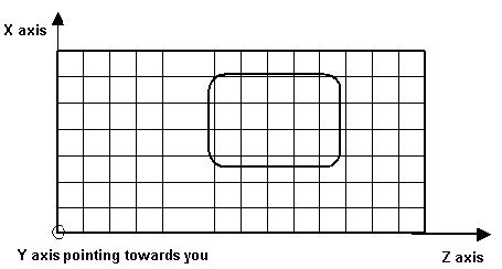
OptiFDTD is a powerful, highly integrated, user-friendly software that allows computer aided design and simulation of advanced passive photonic components. The OptiFDTD software package is based on the finite-difference time-domain (FDTD) method. The FDTD method has been established as a powerful engineering tool for integrated and diffractive optics device simulations. This is due to its…
Wave Setup Introduction
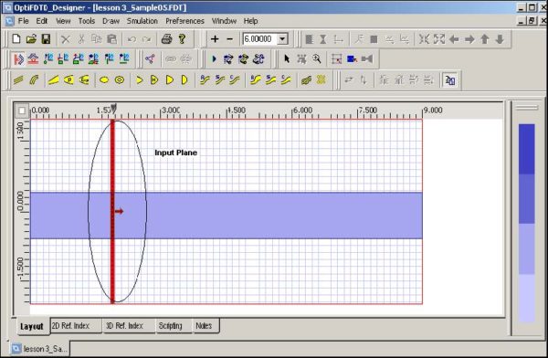
OptiFDTD contains more features in the Input Wave set up and the simulation set up. The excitation set up for the simulation is done by the Input Plane which contain the following features: Time Domain Input Wave formation Continuous Wave with single wavelength Pulse wave with broad band spectrum Transverse field distribution Modal Input Gaussian beam…
Power Calculation and Poynting Vector

For the z-direction propagation wave. The total power in x-y plane can be divided into two power values: x-direction polarized z-direction propagation power (Pz-x) and y-direction polarized z-direction propagation power (Pz-y). The corresponding formulas are: x-polarization power y-polarixation power Total power where the cap dot indicates the complex value that comes from the DFT calculation, and…
References
[1] Aleksandar D. Rakic, Aleksandra B. Djurisic, et. al., “Optical Properties of Metallic Films for Vertical – Cavity Optoelectronic Devices”. 1998 Optical Society of America, August, Vol. 37, No. 22, Applied Optics, pp. 5271-5283. [2] M. I. Markovic and A. D. Rakic, ” Determination of reflection coefficients of laser light of wavelength from the surface of aluminum…
PML Boundary Conditions

The basic FDTD algorithm must be modified at the boundaries of the computational window where suitable numerical absorbing boundary conditions (ABC) are applied. This is one of the most challenging parts of FDTD simulations. There are several choices for the type of boundary conditions. The Perfectly Matched Layer (PML) boundary conditions have the best performance.…
PMC/PEC Boundary Conditions and Plane Wave Simulation
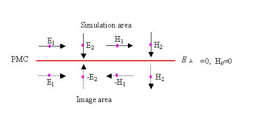
OptiFDTD now has options to use Perfect Electrical Conductor (PEC) and Perfect Magnetic Conductor (PMC) boundary conditions. You can choose which boundaries use the new conditions, and Anisotropic PML can be used for the remaining boundaries. With this PEC/PMC/Anisotropic PML combination, the following simulations may be obtained: Plane wave simulation Domain reduced simulation for symmetric,…
Incident Wave Source Excitation – Total/Reflected Field Formulation
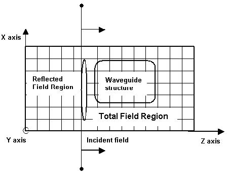
The FDTD numerical scheme yields the solution of an initial value problem. At the first time step of the simulation all the fields are set to zero. The algorithm needs the initial field excitation that will be propagated through the computational domain. The FDTD Total/Reflected Field formulation gives the methodology in defining a +Z propagating…
PBC Boundary Conditions
This version of OptiFDTD provides the option to use simplified Periodic Boundary Condition (PBC). PBC can work with other boundary conditions such as Anisotropic PML, PMC, and PEC. With PBC, you can generate a simple plane wave simulation or periodic layout simulations. The simplified PBC is based on the Bloch’s Theorem: For the periodic layout,…
CW Excitation
In CW excitation, the time dependence of the incident field is a single frequency sinusoidal function. For example the incident Ey field has the following form: where A is the field amplitude, AF(x, zinc) is the transverse field distribution at the incident plane location zinc. The initial phase offset θi is the phase difference between points in…
Pulsed Excitation
For pulsed excitations the incident field has the form: where is the pulse envelope function, toff is the time offset and t0 is the pulse width parameter. For pulsed excitations the time stepping continues until the desired late-time pulse response is observed at the field points of interest.
Point Source
This version of OptiFDTD includes a new type of excitation – Point Source. Point source can also be referred to as a radiation source. For this new source, the input wave is only functional with one field component at one single point. You can specify which field component is required to add this source. In the case…
Gaussian Beam Size

In OptiFDTD, transverse Gaussian Beam is expressed as where x0 is the center position and T is being called as half width. In general, Gaussian Beam radius is the radius at which the field amplitude and intensity drop to 1/e and 1 / e2, respectively. Gaussian Beam Size or Gaussian Beam Spot size is the beam…

