Constant Dielectrics

Constant dielectric material is expressed by a complex refractive index value ( ) or relative permittivity value (εr). Here, n is the refractive index indicating the phase velocity informaiton in the medium, while K is called the extinction coefficient, which indicates the amount of absorption loss when the electromagnetic wave propagates through the material. Note that…
Lossy Dielectrics

Before proceeding with a more detailed description it should be emphasized that the fact that in the time domain all the fields (Hx, Ey, Hz) are real quantities. Thus, accounting for loss is possible only through a non-zero conductivity σ of the medium: where Here we have assumed that and corresponds to time-to-frequency domain Fourier transform.…
Lorentz-Drude Model

By Lorentz dispersion materials, we mean materials for which the frequency dependence of the dielectric permittivity can be described by a sum of multiple resonance Lorentzian functions: where ω0m are the resonant frequencies Gm is related to the oscillator strengths Γm is the damping coefficient ε∞ is the permittivity at infinite frequency X0 is the…
Nonlinear Material
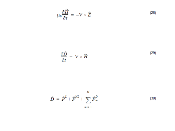
In general, the nonlinear behavior is due to the dependence of the polarization P(t) on the applied electric field, E(t). Assuming an isotropic dispersive material, Maxwell’s equations are: where PL represents the linear polarization, in general is the dispersive polarization which is controlled by Lorentz model in Equation 20 and denotes the nonlinear polarization. The nonlinear…
Dispersive 2nd-Order Nonlinear Material

In this model, the electrical displacement D is where εL is the linear relative permittivity and X(2) is the second order isotropic susceptibility. They are the real values. In order to simulate second order nonlinear effect, you should input two parameters: the linear relative permittivity εL and the second order isotropic susceptibility X(2).
Dispersive 3rd-Order Nonlinear Material

Like the second-order nonlinearity, OptiFDTD takes third-order susceptibility to calculate the nonlinear polarization where εL is the linear relative permittivity and χ(3) is the third order isotropic susceptibility.
Dispersive Kerr Effect
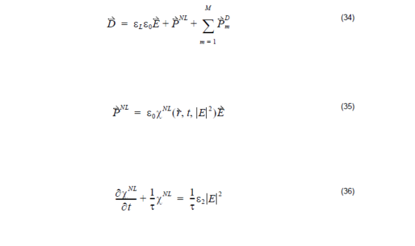
If the time scale over which the medium changed is greater than the pulse width, we should take into account the effects of the finite response time of the medium. Followed by Prof. Richard W. Ziolkowski ‘s work [1]-[4], OptiFDTD treats the nonlinear effect with a finite response time as well as an instantaneous manner…
Dispersive Raman Effect
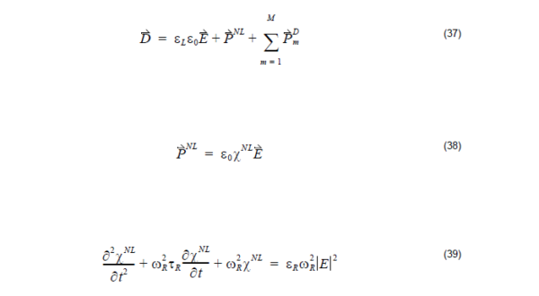
Raman model allows another way to simulate the nonlinear phenomenon where the nonlinear susceptibility was modeled by a second-order derivative equation which is related to the resonant wavelength and the response time where εL is the linear relative permittivity XNL is the nonlinear susceptibility τ is the response time εR is Raman model permittivity ωR…
Analyzing 1D Photonic Crystals (Bragg Gratings) Introduction
The simplest photonic crystal consists of alternating layers of material with different dielectric constants. Such multilayer structures have been widely studied and are frequently referred to as Bragg gratings. In this tutorial we design simple Bragg Grating that consists of alternating layers with permittivity contrast 1/13 as discussed and analyzed in [1]. We will show…
Define the Lattice Structure
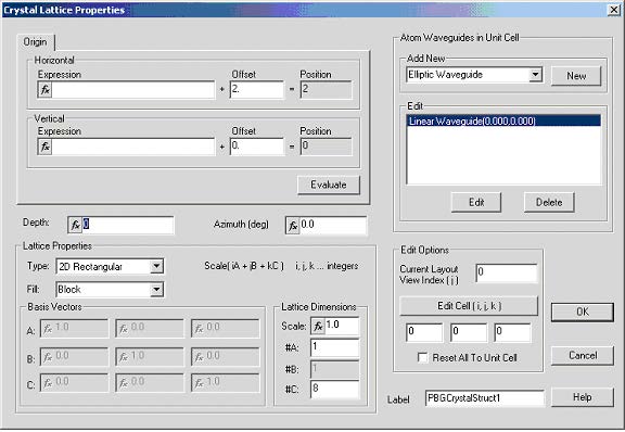
Note: For the details on how a lattice can be created, please refer to Lesson 3— Photonic crystal and photonic band gap simulation and Lesson 9—FDTD Band Solver. For the details on how material and waveguide profile can be created, please refer to Lessons 1 through to Lesson 9. We start investigating system of equally…
Nonlinearity Simulation
To observe nonlinear effects in common used materials, a high-intensity light source is required. You should pay special attention to the input wave amplitude and/or the power level; each model with different parameters may need different input power or amplitude. If the input power is too low, you may not observe the nonlinear phenomenon. If the power is too…
Lorentz-Drude Model in Frequency Domain
It has been shown [1] that a complex dielectric function for some metals and surface plasmas can be expressed in the following form: This form separates explicitly the intraband effects (usually referred to as free electron effects) from interband effect (usually referred to as bound-electron effects). The intraband part εfr ( ω ) of the dielectric function…
PWE Band Solver Parameters
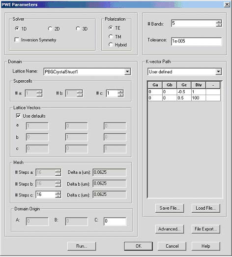
Open PWE Parameters dialog box (Simulation->PWE Band Solver Parameters…) Figure 4: PWE parameters dialog box Unless stated otherwise use default values. In the Solver group select 1D, TE Polarization. Domain parameter group gives you the option to modify the lattice vectors, mesh size as well as simulation center. Select Use defaults in ‘Lattice Vectors’ group. The…
Technical Support
If you purchased Optiwave software from a distributor that is not listed here, please send technical questions to your distributor. Optiwave Systems Inc. – Canada/US East Tel – (613) 224-4700 E-mail – support@optiwave.com Fax – (613) 224-4706 URL – www.optiwave.com Optiwave Europe – Europe Tel – +33 (0) 494 08 27 97 E-mail – support@optiwave.com Fax – +33 (0)…
Discretized Fourier Transform (DFT) and Fast Fourier Transform (FFT)

As a time domain simulation method; FDTD can get all the relevant spectral response with a single simulation. To get the spectral response, you need to use the DFT, FFT, and Analysis. Discretized Fourier Transform gets a single wavelength response from a time series. where s(n) are the time domain response, N is the number…

