
Base
| Full Name | Tung Tran Van |
| Organization | hhhhhhhhh |
| Job Title | mr |
| Country |
Forum Replies Created
I have uploaded my project simulating Raman Amplifier which compensating loss of 100km fiber, but it does not work. Plz help. Thanks
Attachments:
I have same problem . Signal is not amplified when using coupler. Plz help me. I use Optisys v14. Thanks
In theory, Raman amplifier’s NF is small (or even negative), but in the sample .osd file, NF is very high. How to reduce it to resemble theory???
Could you run my attached project and see if there is error?
Thanks you
My laptop has 8GB ram and optisystem consume only about 30% memory when calculating. so I think the cause is not due to weak laptop configuration.
I use Optisystem v7.0 and OS windows 10
Thanks FAYIQA NAQSHBANDI
as I know, a iteration parameter is often used in the bidirectional or ring network design . If my system is the point – point transmission , it can improve ouput OSNR of the ORA ?
Hi all,
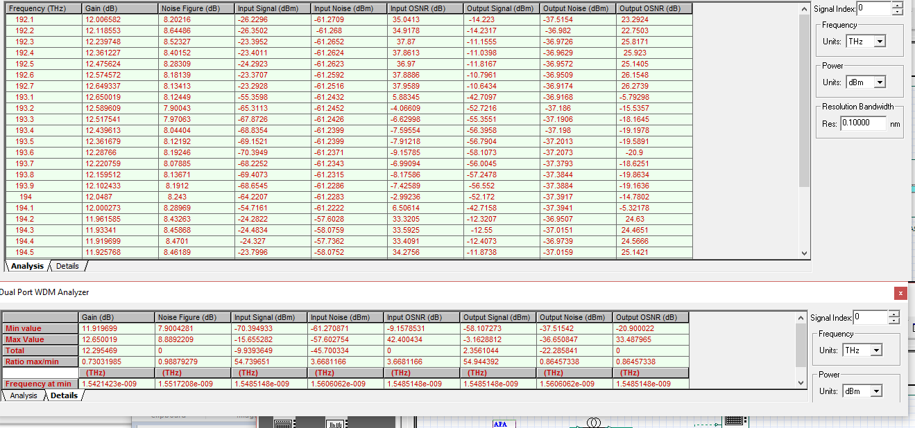
in theory, an optical Raman amplifiers (ORA) increases the OSNR of input signals, but my designed ORA reduces OSNR wdm channels greatly.
what should I do to improve my ORA?
Thanks all
Yep Ranjeet Kumar.
why those BER analyzers dont work? Is my project wrong or does optical ring controller work incorrectly?
any one help me? I think the optical ring controller works incorrectly.
Hi alisu and Ranjeet Kumar
In a project “Interchannel crosstalk at ADM in a ring network”, I have replaced the photodetector PINs and filters by optical receivers.
I dont understand why I just measured BER of 2 nodes (node 1 & node 4).
?
I attached my project.
Attachments:
Thanks alistu
I used DCFs in every nodes, they are between PAs & OAs. I set dispersion.dat for SMFs (G652) & DispersionDCFNew.dat for DCFs (named DCMs). So I think dispersion is compensated. Moreover, the bad received signal only at the nodes with Raman Amps.
Attachments:
Hi all.
Because my project is so complicated, I have deleted some components in it to look better. At some nodes with Raman Amp (node3, node 4), the received signal quality is so bad, Q factor is low. Plz, give me a suggestion to improve system performance.
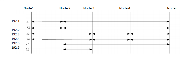
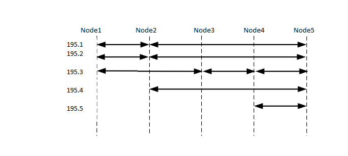
I attach my project with wavelength assignment schemes.
Thank you so much.
Thanks all.
@Fayiqa Naqshbandi: :(. I’m using OptiSys v7, so I can’t open your osd file.
But when increasing the input laser power, Optisys will caculate too slowly because of nonlinear effects. 🙁