
- This topic has 23 replies, 3 voices, and was last updated 10 years, 3 months ago by
 alistu.
-
AuthorPosts
-
-
February 12, 2016 at 12:38 am #29608
Tung Tran Van
ParticipantI have to simulate a realistic DWDM system, so I can’t use a ideal MUX. But BER is bad (~10^-7) (no optical fibers & amplifiers), while using the ideal MUX, BER is very low.
How do I optimize MUX’s paramaters to improve BER (~10^-12 – 10^-9). Thanks.
I attached my tesing project. -
February 12, 2016 at 1:26 am #29611
 alistuParticipant
Hi Tung,
In order to improve the performance of the system with real WDM components, you need to consider the bandwidth defined in the WDM MUX and DEMUX the same as the transmitted bandwidth. I suggest changing it to 11 GHz or 12 GHz (which is about 0.1 nm). The ideal MUX gives all the bandwidth they need and that’s why the signal is better.
Regards
-
February 12, 2016 at 5:47 am #29634Participant
Thanks alistu. I got a better perfomance (~10^-10) with MUX/DEMUX’s bandwitdh 11 GHz.
Could you tell me which component I can check to know the transmitted bandwidth? A Laser?-
February 12, 2016 at 6:10 am #29637alistuParticipant
You’re welcome Tung. You can use an optical spectrum analyzer in the transmitter after the signal for any of the spectrum channels is produced. In case of your system, if you increase the bandwidth of the MUX even further, you’ll notice the performance is improved. This shows you should still increase it further.
-
-
-
February 12, 2016 at 1:38 pm #29659
 gaganpreet KaurParticipant
Alistu i need to understand theoretical relationship between WDM transmitter BW and MUX bandwidth.i was unable to open the file this hour coz optisystem is available only during working hours at college . but i have never optimized mUx BW and a s result many times i received no output BER or Eye diagram but admitting it i was not even aware of this thing. i will try on my design but i need to know criteria of matching bandwidth of MUX/demux with WDM transmitter BW.
-
February 12, 2016 at 9:28 pm #29665alistuParticipant
The bandwidth of each channel in WDM depends very much on the bit rate of that channel and the coding scheme adopted. I have noticed in many cases they consider the bandwidth about ” 0.6*Symbol Rate “. To optimize the dedicated bandwidth, you may need to have a trade off between Q-factor and bandwidth efficiency sometimes.
-
-
February 13, 2016 at 12:01 am #29670Participant
I read some dwdm mux/demux’s datasheet, it usually has a 3dB filter bandwidth of 0.1 nm , even up to 0.45 nm. When increasing the bandwidth of mux/demux, the system performance increases greatly.
But I’m getting a problem, when I use optical fiber & 2 amplifiers: Boost Amp – BA & Pre Amp – PA, I dont know why calculating optical fiber is extremely slow. I have waited 10 minutes and it has not finished yet. When deleting the BA, it run faster.-
February 13, 2016 at 1:00 am #29674alistuParticipant
The reason for the calculations taking up so much time in your simulation is the fact that too much power has been injected into the optical fiber and as a result, nonlinear effects are asserting themselves. You may need to decrease the gain of your power booster to overcome this problem.
-
February 13, 2016 at 1:48 am #29677Participant
I reduced the BA’s gain to 10dB, it run faster. It generated new frequencies because of FWM, but the system perfomance was OK (~10^-10).
Gain range of BA and PA usually are 5-20dB and 5-30dB respectively. Do you know which operating mode of optical amplifier (OA) is set in fact, constant gain or constant output power…? And how much gain should OA set to restrict nonlinear effects? -
February 13, 2016 at 2:14 am #29680alistuParticipant
As far as I know, the gain control and other operation mode options are available in OptiSystem to make working with optical amplifiers easier. In reality, if you need constant gain or any other characteristics, you would have to design the system for that. I have noticed in many applications constant gain was paid attention to.
-
February 13, 2016 at 11:29 pm #29694Participant
Thanks alistu. I dont see receiver sensitivity in receiver components. How can I find it?
-
February 13, 2016 at 11:47 pm #29695alistuParticipant
You’re welcome Tung. Receiver sensitivity is not a factor to be shown in receiver components. It depends on the maximum BER (or minimum Q-factor) defined by the user. I suggest you read the explanation given by Damian in reply to me asking the same question:
-
-
-
February 19, 2016 at 5:50 am #29903Participant
I cant setup a MPO Optimization, I followed pdf file “Optisystem tutorial volume 2”. I cant find “Gain Falatting” type in a Main tab; Contranst tab, Advanced tab….It’s so hard to understand.
I’m using OptiS version 7. -
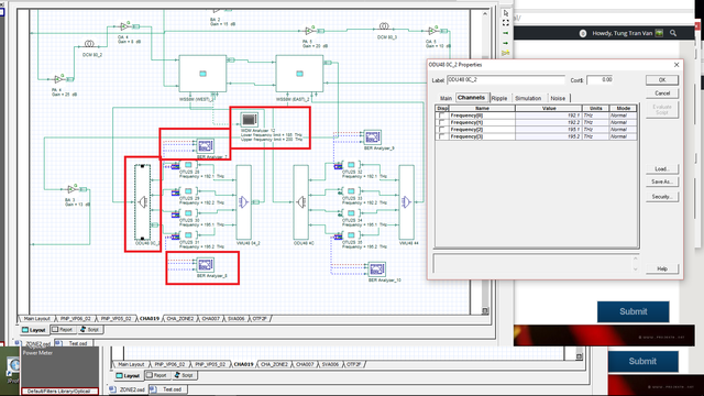
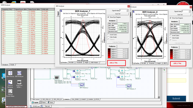
February 21, 2016 at 1:29 pm #29981Participant
A DWDM signal has wavelengths (192.1 THz – 195.5 THz) with similar signal power, noise & OSNR. But the BER of the signal decreases from 192.1 (~10^-12) to 195.5 (~10^-6)? A demux has bandwidth 13 GHz. I dont understand why their BER are different
I attached some photos. Please help me how to fix. Thanks.-
February 21, 2016 at 2:11 pm #29984alistuParticipant
It is really difficult to find the problem with the system implementation unless access to the .osd file is provided. But generally speaking, the optical fibers used in the system have a reference wavelength with regard to which the some of its other parameters are set. This should be taken into consideration.
-
-
February 21, 2016 at 1:33 pm #29982Participant
-
February 21, 2016 at 2:14 pm #29985alistuParticipant
I noticed optical amplifiers being used in your system implementation. Optical amplifiers are also one of the other components who operate within a certain wavelength interval. So make sure their bandwidths are wide enough to cover the whole signal spectrum interval. You might use optical spectrum analyzers for this purpose.
-
February 21, 2016 at 9:43 pm #29986Participant
I created new project Test2 to test OAs. The operating wavelength range: 192.1 – 196 THz. I used OSA and WDM Analyzer for checking, all wavelengths are amplified.
In layout1, everything works OK. But node Node3 in layout2, wavelengths’s BER are different lot (as mentioned above): 192.1, 192.2(~10^-13) -> 195.1, 195.2 (~10^-6)
I attached project Test2.
Thanks -
February 22, 2016 at 6:23 am #29991alistuParticipant
From the image you have attached, I realized the amplification is done for all frequencies as you have mentioned (along with the noise added by amplifiers). However, I ran your Test2 file and the was not any significant difference between the performance of the two channels in terms of BER or Q-factor.
-
February 22, 2016 at 11:59 am #30020Participant
Thanks alistu
I attached the wrong file :D. I have attached a new .osd file shortened from my project. In node3, there are difference between 4 channel’s BER in spite of similar OSNRs.
Thanks -
February 23, 2016 at 6:17 am #30026alistuParticipant
Hi Tung,
The implementation is really complicated and I spent some time following the wires, but I think it would be better to ask you to make the change I would like to recommend yourself. I believe dispersion compensation is not done in an efficient way. It seems the only parameter that you have considered for dispersion is the “dispersion”, and not the “dispersion slope”. This has caused me similar problems in the past. Please see if this is the reason.
Regards
-
-
-
February 24, 2016 at 6:07 am #30086Participant
Thanks alistu. I’ve used files dispersion & dispersionDCF for SMF & DCF and increased OA’s gain, system performance of channels 195.x THz have been better.
-
February 28, 2016 at 12:47 pm #30427Participant
After optimizing pump power and frequencies of Raman Amp for gain flatness, output OSNRs are very low. With several EDFA amplifiers, system performance is so bad.
How can i improve the DWDM system performance using Raman amp?
I attached my project (layout2)
Thanks -
February 29, 2016 at 12:18 am #30434alistuParticipant
You’re welcome Tung. Let’s discuss your new problem in the new topic you have opened for it at https://optiwave.com/forums/topic/how-to-improve-osnr-of-optimized-raman-amplifier/ . Thank you.
-
-
AuthorPosts
- You must be logged in to reply to this topic.