
- This topic has 12 replies, 4 voices, and was last updated 10 years, 4 months ago by
 alistu.
-
AuthorPosts
-
-
November 25, 2015 at 1:25 pm #28073
 Arpita GuptaParticipant
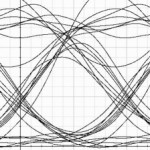
I am getting the any receiver design with optiwave for double weight or MDW Code for with proper simulation with complementary subtraction and Single photo diode detection technique. i am trying to simulate but not getting the proper eye diagram in specified BER Please help me
-
November 25, 2015 at 5:24 pm #28095
 alistuParticipant
Hi Arpita,
Please attach your OptiSystem simulation file (the one with .osd format) so that I would be able to have access to it in order to analyze the system. BTW, can you please elaborate more on “not being able to get proper eye pattern in specified BER”? You mean BER is OK but eye diagram is not?
Regards
-
November 26, 2015 at 8:10 am #28107Arpita GuptaParticipant
this is based on double weight code
110
011i am getting the disturbing pattern. I am providing the .osd file
-
December 1, 2015 at 5:47 am #28255
LALIT VERMA
ParticipantWhy u r not using FBG or optical filter in receiver side,becoz u can get optimum filtering using that.as spectral source slicing is more suitable for wdm.
-
December 1, 2015 at 9:58 am #28267Arpita GuptaParticipant
i am attaching the .osd file. this provide the excellent BER at 311Mbits/s but at the 622Mbits/s or more than this,BER is totally wrong. please provide the support at high data rate
-
December 1, 2015 at 11:40 am #28270alistuParticipant
Hi Arpita,
I simply reduced the number of samples per bit to 64 and got min. BER = 0 for the same system. I have attached the file in which I have even increased the bit rate to 1e9 while the Q-factor is more than 13, suggesting you can even increase the bit rate further that one gigabits per second.
Regards
-
-
December 1, 2015 at 12:37 pm #28273Arpita GuptaParticipant
i am applied the suggested approach in another design, which is based on single photo diode detection (SPD) technique . The concept is given as (double weight)
U1- 1100
U2 0110
U3- 0011i am attaching the .osd file. i am facing same problem. when sample per bit is 64 than all users do not provide the BER at output end.
-
December 1, 2015 at 9:45 pm #28285alistuParticipant
I analyzed the system and unfortunately I couldn’t get all three users to give acceptable results at once. I even managed to get results with Q-factor of more than 200 for the first two channel, while the third one had a really corrupted eye diagram. I hope Optiwave will help you on this, as I have come across this problem before.
-
-
December 3, 2015 at 1:39 am #28349Participant
As u r having three user in SAC OCDMA SPD scheme the bit rate in fiber is going to become 622e006 multiplied by 3. so for three user sample rate should be atleast twice of nit rate that is bandwidth of system 1.866e009 multiplied by 2 so 3.7e009 at least than look at the simulation.
-
December 3, 2015 at 2:21 am #28353alistuParticipant
Hi Lalit,
I have tried to help Arpita by setting different values for sample per bit, but even by choosing much greater values for samples per bit than the aforementioned, I couldn’t get acceptable results for the third user. Can you please see Arpita’s implementation and see if you verify this?
Regards
-
-
December 7, 2015 at 7:31 am #28509
 Eng. YanParticipant
Hi Arpita Gupta,
in order to represent the optical code for each user. you can use even just one optical source. since one source is applicable to support up to 20 wavelengths. in that, you can use WDM Demus to slice the broadband spectrum. As mentioned above, FBG can be used to represent each code length.
Regards
-
December 7, 2015 at 9:45 am #28527Participant
Hi Alyan
u are right but Arpita is using LASER which is going to give better results as compared to an In coherent optical source .PIIN noise would make the system more MAI by using Incoherent source the BER Achieve in previous results will also degrade.
Although she will get results for MDW code using De Mux as splicer.Thanks
with regards. -
December 7, 2015 at 10:08 am #28529alistuParticipant
The system Arpita has implemented is working fine for two channels and gives very good results for them, while it is not working for the third one (while the same sampling rate and so on is being used for all users). this may imply the system is being implemented correctly. I am very interested to know how to fix this.
-
May 22, 2018 at 9:42 am #48823
 Hardik JoshiParticipant
Hello,
At Receiver of user 3 add another FGB with 1550.6nm at subtraction side (like receiver of user 2) is making eye more clear like user 1 and 2.
-
-
AuthorPosts
- You must be logged in to reply to this topic.