
- This topic has 26 replies, 8 voices, and was last updated 8 years, 1 month ago by
Manoj Kumar.
-
AuthorPosts
-
-
March 8, 2016 at 7:04 am #31804
 SAHIL SINGHParticipant
How can i improve my BER and quality factor of my system. I am taking length 100km and power 0 dbm. Also my result values change evrytime i simulate.
please can anybdy tell me what is wrong….
thanks -
March 8, 2016 at 8:05 am #31892
 ZULKARNAINParticipant
Hi Sahil.
Well in my opinion You can improve the quality factor of your system by increasing the input power of your system,but not so high because at high powers the non-linearity effects come into existence.
Also you can use DCF( dispersion compensating optical fiber) and optical gain amplifiers to increase the quality factor as well as transmission distance of your system.For the problem of change in results i am attaching a link for your reference which might help you.
-
March 8, 2016 at 12:23 pm #31931SAHIL SINGHParticipant
Thanks zulkarnain. I may try it on my architecture. I am grateful
-
March 9, 2016 at 1:37 am #31986ZULKARNAINParticipant
You are most welcome sahil singh…
-
-
-
March 8, 2016 at 9:08 am #31895
 aasif bashir darParticipant
hi sahil,
let me break down you query into two parts.
1. how to improve your BER with 0dbm and 100 km lengthwell it will depend on the data rate you are using, well upto 10 gbps the quality factor will be arround 6-9,but for higher data rates, you have to use some kind of dispersion compensation technique(either using DCF, ideal FBG dispersion compensator in optisystem)
the BER can be improve with the use of pre amplifier before the detector i.e pin or APD.
with regards-
March 8, 2016 at 12:27 pm #31932SAHIL SINGHParticipant
hi asif. I am new to optisystem software. I tried increasing power and the results were much better but when i tried to increase the fiber length the BER got increased and also q-factor reduced. I shall try ur suggestions and see the results again. i hope it works this time.
thanks-
March 8, 2016 at 1:43 pm #31943ZULKARNAINParticipant
Hi Sahil…
Well according to myself with increase in optical fiber length dispersion increases,so you can either use a amplifier or dispersion compensating fibers.
Also i would like to say that you cannot increase the input power indefinitely as it will lead to non-linear effects.
But please first confirm the above.
Hope you will get some benefit from my explanation. -
March 8, 2016 at 2:54 pm #31952
 Aabid BabaParticipant
Hello zulkarnain,
You have rightly mentioned about increasing power indefinitely because it sometimes has an adverse effect on our system design and that’s the reason ITU-T has standardized values for every parameter for each system implementation in different scenarios. So he can vary any parameter but upto a certain limit as recommended by ITU-T. I hope you got my point.Regards
-
-
-
March 8, 2016 at 9:11 am #31896aasif bashir darParticipant
2.why does your results very and are different for different simulations?
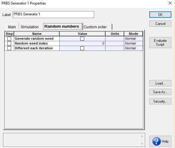
well it is due to random ness of some of the components like cw laser, PBRS, fiber , PIN or APD. the simple way to reduce it is to untick the the random seed of these components in there parameter window.
hope your problem is solved sahil.
with regards
-
March 8, 2016 at 10:53 am #31905
 TanveerParticipant
hi Sahil singgh…..
I agree what aasif told you to do.
It can be because of random seed thing. you should double click on every component you have used in your design especially the active components , you may see a simulation tab namely random , click on that and untick the generate seed option. It will definitely make your results stable. I hope you fing it helpful.
i am attaching the snapshot too……
regardsAttachments:
-
March 8, 2016 at 10:45 pm #31963SAHIL SINGHParticipant
thank u tanveer. All the answers are related almost though very helpful in fact. I appreciate ur responses and also for uploading the photo. it really helped a lot getting it quickly.
thank u again
-
March 8, 2016 at 11:21 am #31911Aabid BabaParticipant
Hi sahil,
As mentioned by asif you need to go through the same sequence. I would first suggest you to please tell us what data rate is requirement of your system…
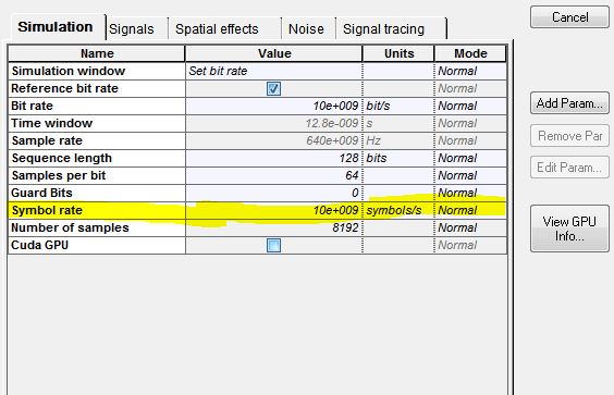
Also instead of increasing power at first place try to using ideal components and make sure your symbol rate is higher than the chosen bit rate.
Here i would suggest to increase power if ever need arises. Hope these suggestions will work for you.regards
-
March 8, 2016 at 10:49 pm #31964SAHIL SINGHParticipant
hi aabid. i have to design a system for my lab project where i have to get good performance for 150 km fiber length and also for data rate 20 gbps. we have to also compare results at different data rate like 5 gbps, 10 gbps and 20 gbps.
plz can u tel me where i can increase the symbol rate. and what about power?? can i use more than 0 dbm?
thanks i advance-
March 9, 2016 at 1:17 am #31980Aabid BabaParticipant
Hello sahil,
Here i am attaching the screenshot of the simulation layout where you will be able to change the symbol rate for your system design.
I would recommend you to keep power as low as possible because whenever you try to increase power non linearities creep in. But you can still increase to a certain limit. Hope you would find it helpful
RegardsAttachments:
-
March 9, 2016 at 2:55 am #31995SAHIL SINGHParticipant
Hello aabid, I tried it and the result was much better than the previous attempt. My quality factor also increased from 15 to 21..
however i did not increase the power. i only changed the bandwidth of filter and the symbol rate. i made my symbol rate greater than my bit rate. the results were much much better. thanks anyways
-
-
-
March 9, 2016 at 12:02 am #31965Aabid BabaParticipant
Hello sahil,
I understand what you say and what your requirement is. Firstly , i am sorry i can’t send the screenshot where i could show you how and where to change symbol rate at the moment. Shall attach it once i reach the university lab. Please check the simulation layout parameters , there is where you find it. Hopefully i will upload it in some time.
Secondly i want to tell you that you can increase power to any value as per your requirement but within ITU-T standards. Increase power to 5dbm. It will work fine..hope it helps you.Regards
-
March 9, 2016 at 12:06 am #31968aasif bashir darParticipant
hi sahil singh,
150 km fiber lfor data rate 20 gbps and compare results at different data rate like 5 gbps, 10 gbps ;;;; is quit easy task
first you need some dispersion compensation method , e.g break 150 length span in two i.e 75 and 75.no w in each 75km use 60 km single mode fiber ans 15 km ad dispersion compensation fiber.
please also increse upto 5dbm
with regards
-
March 9, 2016 at 2:58 am #31997SAHIL SINGHParticipant
hi asif.
i am new to this optisystem tool. i am designing a simple transmitter receiver system in which i have to take results at 10 Gbps for 100 km fiber distance.
i am not aware of the dispersion compensation technique. i have studied it theoretically but i am not aware of doing it in the optisystem. Anyway thanks a lot for the reply.
-
-
March 9, 2016 at 3:38 am #32005
 umer syedParticipant
hi sahil singh,
the dispersion compensation fiber (DCF) is the same fiber component as that of the single mode fiber, but here you have to change the dispersion of the fiber which is originally given as the 16.75ps /kn.nm.change it to e.g -38ps/km.nm
hope you will d it and reply soonwith regards
-
March 9, 2016 at 4:35 am #32020SAHIL SINGHParticipant
Hi umer syed
I really appreciate your valuable efforts and thank you for such valuable information… I will surely try it.. -
March 9, 2016 at 6:06 am #32031
 Ranjeet KumarParticipant
Hi Sahil,
First you should clear the type of system you are designing and having problem with.
In wdm system, if you increase the power of Laser, the BER and Q-factor will increase, in addition to this if you decrease the bit rate in global parameters the BER and Q-factor may increase, some modulation formats cause less the BER and Q-factor while other give large. -
March 9, 2016 at 11:59 am #32097SAHIL SINGHParticipant
Hi Ranjeet kumar,
I am indeed designing a wdm system… Can you please specify which modulation formats cause less BER ?
Thanking you for your earlier responsose…-
March 9, 2016 at 1:33 pm #32142Aabid BabaParticipant
Hi sahil singh,
Well i would like to say that it depends upon the requirement and application aspect of your system design. if you sole purpose is to reduce BER and achieve high quality factor then as asif mentioned rightly you can use modulation techniques like QPSK, DPSK , QAM and its other classes.
I hope it would help you.Regards
-
-
March 9, 2016 at 1:06 pm #32124aasif bashir darParticipant
hi sahil,
i suggest you use phase modulation schemses like psk, dpsk, qpsk,
with regards
-
March 9, 2016 at 1:17 pm #32126Ranjeet KumarParticipant
Hi sahil,
If you will use advanced modulation formats like CSRZ, DRZ, MDRZ, DPSK AND QPSK , it will give propagate over larger distance for appreciable Q-factor and minimum BER.
I have designed 8 channel wdm system using different advanced modulation format mentioned above. I think MDRZ IS best of csrz and drz.
Here, i am uploading osd file of WDM SYSTEM USING MDRZ modulation format.
HOPE THIS will help you to understand things more properly.Attachments:
-
March 9, 2016 at 1:23 pm #32133SAHIL SINGHParticipant
Hi ranjeet kumar,
thank you for uploading the osd file.. This indeed will help me to understand the design in a more efficient way… -
April 11, 2016 at 7:10 am #36252
Manoj Kumar
ParticipantHi Sahil.
Well in my opinion You can improve the quality factor of your system by increasing the input power of your system,but not so high because at high powers the non-linearity effects come into existence.
Also you can use DCF( dispersion compensating optical fiber) and optical gain amplifiers to increase the quality factor as well as transmission distance of your system.For the problem of change in results i am attaching a link for your reference which might help you.
-
-
AuthorPosts
- You must be logged in to reply to this topic.