Optical Time Domain Multiplexing (OTDM) Design
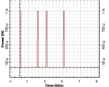
The objective of this lesson is to demonstrate the possibility of simulating a packet-interleaved operation using OptiSystem.
In this case, the data stream externally modulates a periodic stream of narrow pulses.
Because the bit interval is T, the separation between successive pulses is also T.
System Performance Analysis Using Script Automation
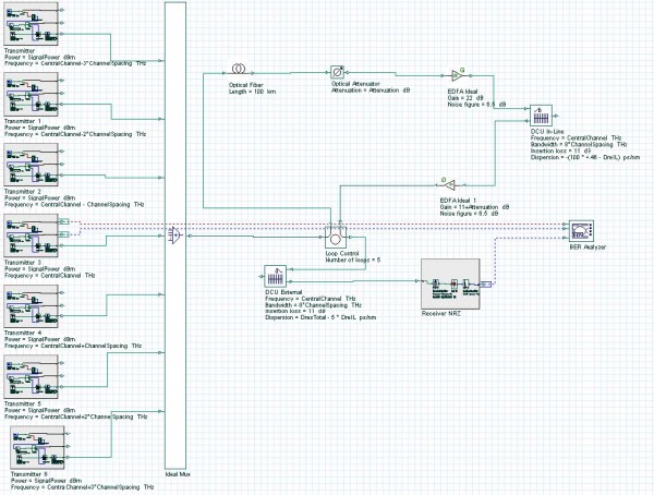
The objective of this lesson is to demonstrate the performance analysis of a system using the script page to vary the system parameters and store the results.
Sometimes, to analyze the system performance, several parameters in the system are varied and the results for each different configuration have to be stored.
BER Calculation Using the BER Test Set

This example demonstrates the use of a BER test set component to calculate the system performance. Samples: NRZ_BERestimation.osd NRZ_BERcalculation.osd Fig. 1 shows the system layout designed that will have its performance evaluated. For an initial estimation on the BER value, a BER analyzer is used to estimate the bit error rate based on a Gaussian…
Comparison of RZ and NRZ Modulation Formats for 40 Gb/s Systems
Most installed fibers are standard single mode fibers (SMF) with high group velocity dispersion values ( ~ 16ps/nm/km ) at 1.55 µm. To achieve a good level of bit-error- rate (BER) as well as to enable larger repeater spacing and larger signal-to-noise ratio (SNR) in this type of fiber, it is very important to consider…
16 Channel WDM System Design
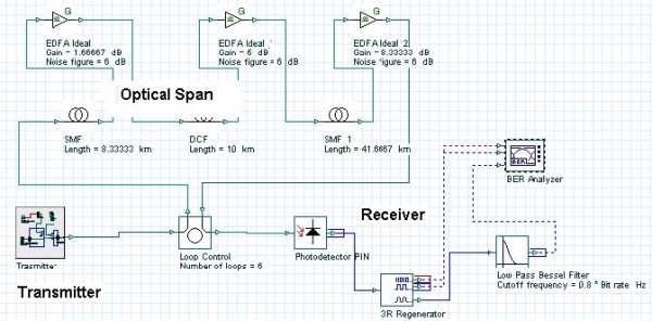
This lesson demonstrates the basic features of a typical WDM optical communication system and shows the basic design steps with OptiSystem. In this lesson we will develop a simple, realistic WDM communication system. The performance of the system will be shown and compared with published results. The impact of various physical effects accompanying the light…
WDM Components – Tunable Filters
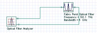
OptiSystem component library includes different types of components for WDM systems, the tunable optical filters include Fabry-Perot filters, Mach-Zehnder interferometers, and grating based filters. Fabry-Perot filters Fabry-Perot filter.osd shows the transmission of a Fabry-Perot filter used as a tunable optical filter (see Figure 1). The frequency spacing between two successive transmission peaks is know as…
WDM Components – AWG Demultiplexer
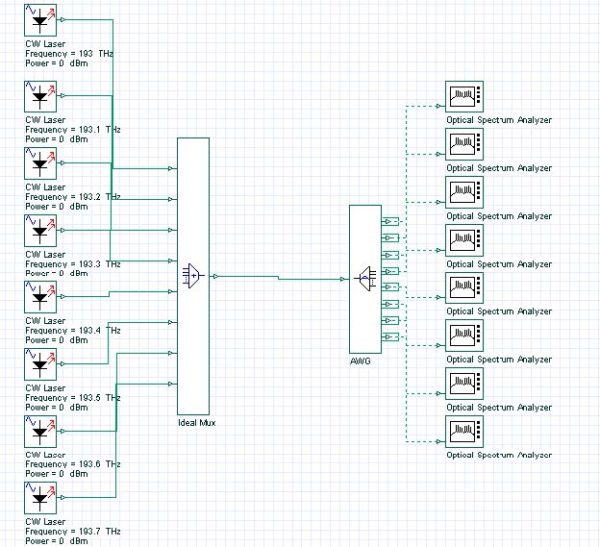
Fiber Bragg gratings can be used for making all fiber demultiplexers. AWG Demultiplexer.osd (see Figure 1) shows an Array waveguide grating (AWG) demultiplexer. Figure 1 AWG Demultiplexer The OSA at the AWG output shows the selected WDM channel. For the first channel, the results are shown in Figure 2. Figure 2 AWG OSA Input The AWG…
Broadcast Star Coupler
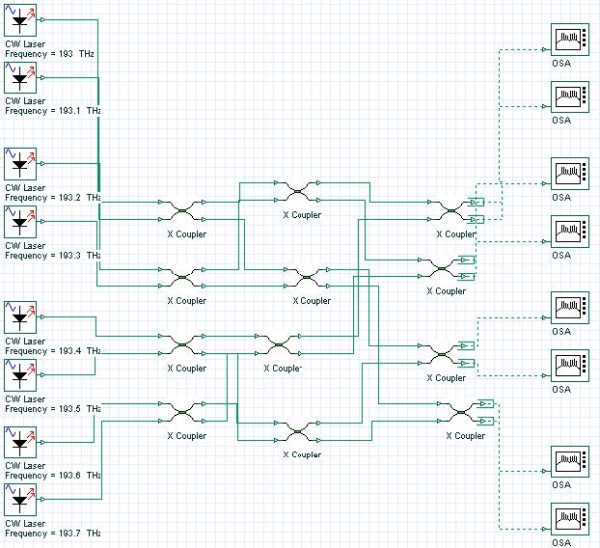
The role of a star coupler is to combine the optical signals entering from its multiple input ports and divide it equally among its output ports. Broadcast Star Couplers.osd show a star coupler with 8 input ports; each port has a transmitter working in different wavelengths. Figure 1 – Broadcast Star Couplers The output of…
Optical Cross-Connects
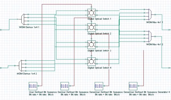
The development of wide-area WDM networks requires wavelength routing that can be reconfigure the network while maintaining its transparent nature. OXC Project.osd shows an optical cross connect with 2 input and 2 outputs, each port accommodate 4 wavelengths: Figure 1 – Optical Cross-Connect
Configurable Optical Add-Drop Multiplexer
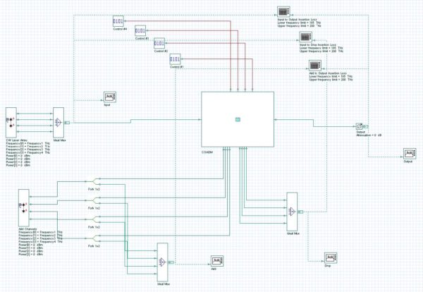
Designed to deliver increased functionality and flexibility necessary for today’s advanced optical networks, the COADM demonstrated in project COADM 4×4.osd enables up to 4 channels to be independently added and dropped at will. The system layout is presented in Figure 1; the input of the COADM is connected to a CW Laser Array, which generates…
Advanced Modulation Formats
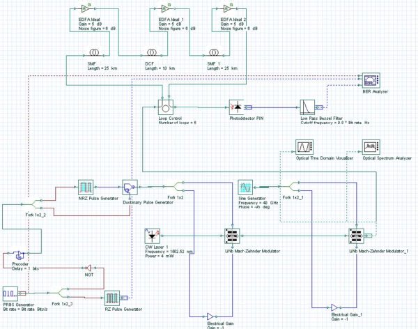
The objective of this lesson is to demonstrate the ability to modulate optical signals in formats different of the common RZ and NRZ. In this tutorial our goal is to generate a 40 Gb/s optical signal in the proposed modulation formats: duobinary modified-duobinary (MDRZ) Carrier-suppressed RZ (CSRZ), DPSK and DQPSK formats To generate the…
Conventional Duobinary Transmitter
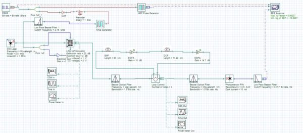
Project ODB with Filters ModulationSystem.osd (Figure 1) demonstrates a system that is an optical duobinary system based on a conventional duobinary transmitter implemented by using a Mach-Zehnder modulator driven with three-level signals generated by using electrical low-pass filters. Figure 1 – Optical duobinary system
Modified Duobinary Transmitter
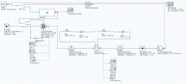
Project MODB_ModulationSystem.osd (Figure 1) demonstrates a system that is an is optical modified duobinary RZ transmission system, which is equivalent to a duobinary carrier suppressed. Figure 1 – Modified duobinary system
Interferometer Characterization
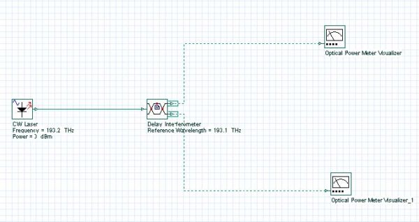
The objective of this lesson is to demonstrate the response of the delay interferometer when the wavelength and polarization of the input signal changes. The objective of this lesson is to demonstrate the response of the delay interferometer when the wavelength and polarization of the input signal changes. Figure 1 shows the system layout designed.…
Fundamental and Higher Order Solitons
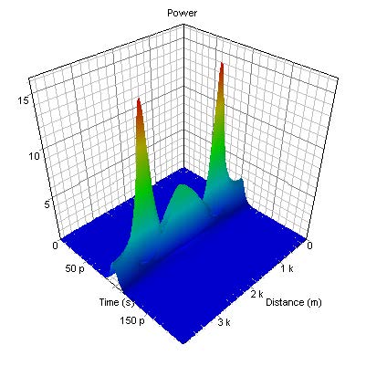
This lesson demonstrates that the exact balance between the effects of SPM and GVD leads to the formation of a fundamental soliton – a light pulse that propagates without changing its shape and spectrum, and shows some basic features of the higher-order solitons. Figure 1 shows the layout and its global parameters. Figure 1: System…

