Polarization Mode Dispersion Models
Polarization mode dispersion In ideal single-mode fibers, propagation constants of the two polarization Eigenmodes are degenerate. In real telecommunications fibers, perturbations act on the fiber in a way that it induces a birefringence, which splits this degeneracy. Consequently, when a pulse is launched in a fiber, it gives rise to a differential group delay between…
Technical References
[1] M. J. Adams, “An introduction to Optical Waveguides,” John Wiley & Sons, 1981. [2] M. Artiglia, “Mode field Diameter measurements in single-mode optical fibers,” J. Lightwave Tech. Vol. 7, no. 8, pp. 11391152, 1989. [3] F. Bruyère, “Effets de Polarisation dans les Systèmes à Amplification Optique de Longue Distance”, Ph.D dissertation, Univ. of Paris XI Orsay,…
Dispersion Flattened Fiber
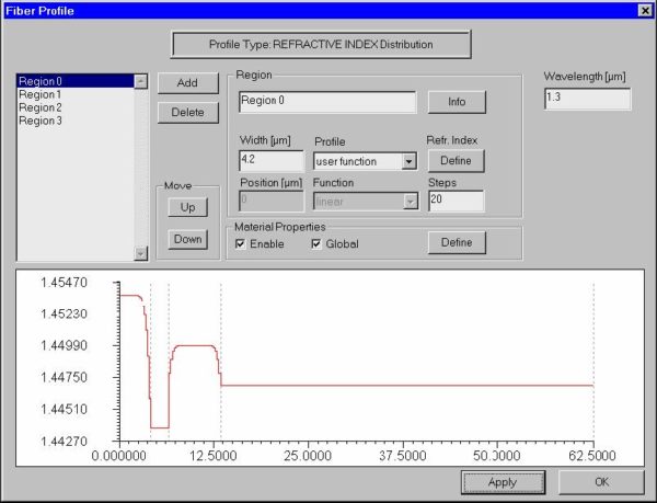
In this example, we will simulate a dispersion flattened fiber. We will also demonstrate the use of the internal scripting language of OptiFiber for defining profiles. You can find this example as the DFF.fcd file in the Samples directory. Defining fiber profile To define a fiber profile, follow these steps: Step Action 1 From the…
File
New command The “New” command opens a new OptiFiber file with empty “Views” window, except the “Material Loss” view. Fiber parameters have default values. OptiFiber creates a default name for the newly opened file. This command can be accessed from: File menu Standard toolbar Open command The “Open” command opens an existing OptiFiber file. The…
View
Status Bar The “Status Bar” command toggles the display of the status bar at the bottom of the OptiFiber workspace window. This command can be accessed from: View menu Navigator command The “Navigator” command toggles the display of the “Navigator” pane in the OptiFiber workspace window. This command can be accessed from: View menu Toolbars…
Fiber
Profile command The “Fiber” command opens the “Fiber Profile” dialog box, where you can design the refractive index profile of the fiber and have access to the dispersion properties of the fiber materials. This command can be accessed from: Fiber menu Fiber Profile icon on the Navigator pane:
Simulation
Modes command The “Modes” command opens the “Modes” dialog box, where you can perform initial calculations and select fiber modes to be calculated further. This command can be accessed from: Simulation menu Modes icon on the Navigator pane: Fundamental Mode command The “Fundamental Mode” command opens the “Properties of Fundamental Mode” dialog box, where you…
Tools
Settings command The “Settings” command opens the “Global Settings” dialog box, where you can set up graphics properties for the output views. This command can be accessed from: Tools menu Table command The “Table” command opens the “Table” dialog box, where you can preview, copy (for pasting in another application, such as Excel) or export…
Window
New Window command The “New Window” command creates a copy window of the active output view window. The program adds a default name to the newly created window. This command can be accessed from: Window menu Cascade command The “Cascade” command creates a cascade view of the output view windows within the OptiFiber workspace. This…
Graph Tools
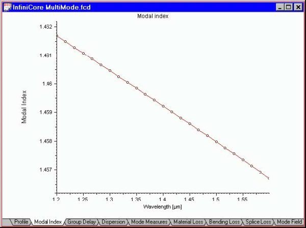
“Joints” command The “Joints” command activates the display of data points in the active output view. The data points are marked as small circles. This command can be accessed from: Graph Tools toolbar Floating menu (right mouse button on a graph) “Zoom XY” command The “Zoom XY” command serves to expand horizontally and vertically a…
Fiber Profile
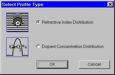
Select Profile Type dialog box Currently OptiFiber supports two types of profiles Refractive index profile Dopant concentration profile The “Select Profile Type” dialog box offers a choice between them. After that it popsup the “Fiber Profile” dialog box. Fiber Profile dialog box The “Fiber Profile” dialog box helps you design the refractive index profile of…
Fiber Modes
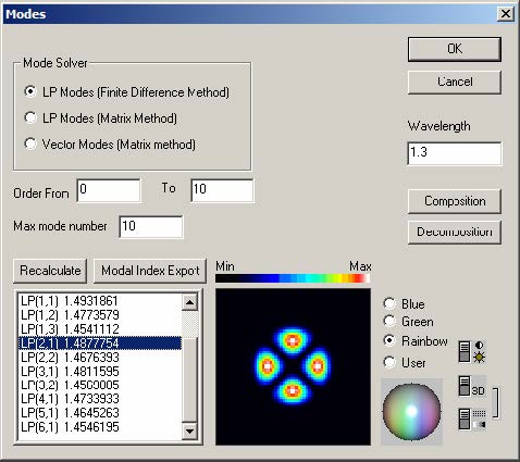
Modes dialog box The “Modes” dialog box allows you to: Select the types of modes you are interested in Select the range of mode numbers you are interested in Find the spectrum of supported modes at the specified wavelength with their mode numbers and effective refractive indices Select a mode or group of modes for…
Fiber Loss
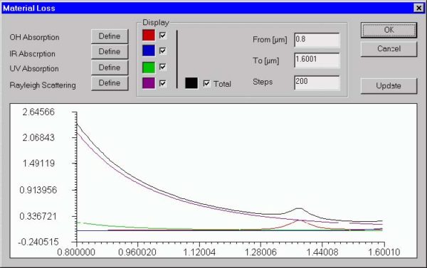
Material Loss dialog box The “Material Loss” dialog box allows you to define parameters for the material loss models and preview them on the attached display. The material loss includes the OH radicals, infrared, and ultraviolet absorption models, as well as the Rayleigh scattering model. To access this dialog box, do the following steps: Step…
Fiber Birefringence
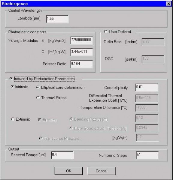
Birefringence dialog box The “Birefringence” dialog box allows you to define parameters of the fiber birefringence model. As described in the “Technical Background”, various mechanisms contribute to fiber birefringence. You can simply define birefringence values or follow one of the OptiFiber models. To access this dialog box, do one of the following steps: Step Action…
Polarization Mode Dispersion
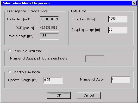
Polarization Mode Dispersion dialog box The “Polarization Mode Dispersion” dialog box allows you to define parameters of the PMD model as well as choose the PMD simulation method as the ensemble simulation or spectral simulation. Theoretically, both methods are equivalent. To access this dialog box, do the following steps: Step Action 1 Select “PMD” on…

