Photonic Crystal and Photonic Band Gap Introduction
OptiFDTD provides comprehensive design, simulation, and post-analysis tools for photonic crystal (PhC) and photonic band gap (PBG) analysis: layout designer provides the tools to define the lattice relation, atom properties, defects, wave path, and observation projects band solver is an independent simulation engine that gives the band-diagram for the defined lattice structure simulator can perform the…
PBG Layout

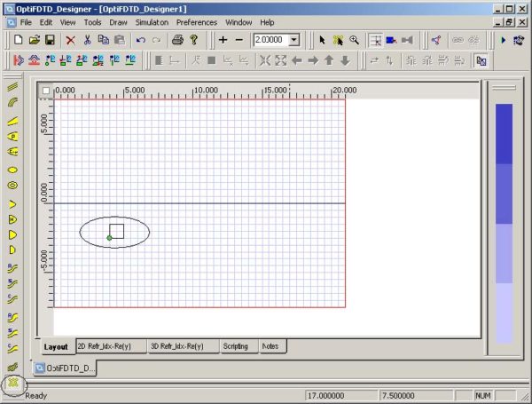
Designing a PBG structure To design a PBG structure, perform the following procedures. Step Action 1 Start Waveguide Layout Designer. 2 To create a new project, select File > New. The Initial Properties dialog box appears. 3 Click Profiles and Materials. The Profile Designer window appears. 4 Under the Materials folder of OptiFDTD Designer1, right-click the Dielectric folder and select New. A new Dielectric material dialog box appears. 5 Type…
Plane Wave Simulation Based on the Periodic Cell of PhC

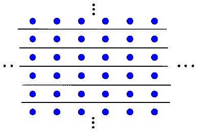
Most of the photonic crystal has the periodic lattice. In some cases, you may want to know the band gap effect for such a lattice. As discussed in the OptiFDTD Technical Background, this task can be simplified in an FDTD simulation using plane wave excitation and PEC/PMC boundary conditions. For example, Figure 100 shows a 2D…
Periodic Boundary Condition for PBG Simulation

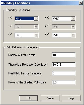
OptiFDTD has options to use simplified Periodic Boundary Condition (PBC). It can work with other boundary conditions such as Anisotropic PML, PMC, and PEC. With PBC, you can simulate a simple plane wave simulation, or a periodic layout simulation. For more information regarding PBC, see the Technical Background. The following procedure is based on . You…

