Fiber Profile

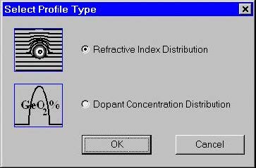
Designing a fiber profile The process of designing a new fiber usually starts by defining its profile. Click the “Fiber Profile” icon in the Navigator pane or double-click the workspace or select the “Fiber/Profile” menu item. Currently two types of profiles are supported: refractive index profile and dopant concentration profile. The “Select Profile Type” dialog…
Calculating Fiber Modes
After having defined the fiber profile the user can proceed with the calculations. Click the “Modes” icon in the “Navigator” pane. The “Modes” dialog box appears. To recalculate this example fiber profile do the following steps: Step Action 1 In the Mode Solver panel, check the LP Modes (finite difference method) option and leave the…
Fundamental Mode
Click the “Scan Fundamental Mode” icon in the Navigator pane. The “Properties of Fundamental Mode” dialog box appears. Do the following steps: Step Action 1 Press the “Calculate” button. The routines calculate all characteristics checked in the Calculate section. In the “Views” window, you can now see graphs of these characteristics. 2 Click the “Modal…
Higher Order Mode
If the current fiber design supports multiple modes their characteristics can be calculated the following way: Step Action 1 In the “Modes” dialog box recalculate and select the higher-order mode of interest. In that example of a typical 65/125 multi-mode graded-index fiber it is LP(3,6) Click the “High Order Mode” icon in the Navigator pane.…
Arbitrarily Selected Group of Modes
If the current fiber design supports multiple modes the characteristics of a group of modes can be calculated for comparison: Step Action 1 In the “Modes” dialog box recalculate and select the group of modes, in this case all the modes from LP(0,1) to LP(2,6) 2 Then proceed to the “Properties of High Order Mode”.…
Cutoff Wavelengths
Click the “Cutoff” icon in the “Navigator” pane. The “Cutoff” dialog box appears. Press “Recalculate” first to obtain the mode list. If the fiber is single-mode, reduce the wavelength value using the edit box with the same name (to 0.5 microns in the picture below). Two types of cutoff calculations are currently supported and respectively…
Birefringence
Click the “Birefringence” icon in the “Navigator” pane. The “Birefringence” dialog box appears. Step Action 1 In the “Birefringence” dialog box, check the “Induced by Perturbation Parameters” option. The “Photoelastic Constants” entries become available. 2 In the “Photoelastic Constants” section, enter: Young Modulus 7750000000, C 3.44e-011, Poisson Ratio 0.164. 3 In the “Induced by Perturbation”…
Polarization Mode Dispersion
Click the “PMD” icon in the “Navigator” pane. The “Polarization Mode Dispersion” dialog box appears. To execute the polarization mode dispersion calculations, leave the defaults and press “OK”. The program calculates the polarization mode dispersion and updates the “PMD” tab in the “Views” window.The “PMD” dialog box appears automatically showing numerical values related to the…

