Introduction
This lesson describes how to modify the refractive index of a waveguide by using the script. The script runs the simulation four times. The refractive index of the waveguide in the first iteration has the StartValue of 1.47. It is increased in later simulations to 1.48, 1.49, and 1.50. The procedures are: • Defining the materials and…
Defining Materials & Channel
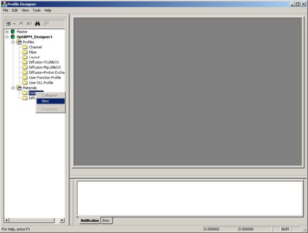
To define the materials and the channel, perform the following procedure. Step Action 1 From the File menu, select New.The Initial Properties dialog box appears. 2 Click Profiles And Materials. The Profile Designer opens and displays the Options dialog box. – Change the Master library path if required, and then click OK to close the…
Defining Layout Settings
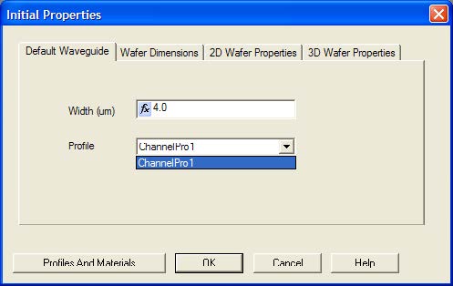
To define the layout settings, perform the following procedure. Step Action 1 In the Initial Properties dialog box, click the Waveguide Properties tab. 2 Type the following value: Width (um): 4.0 3 In the Profile list, click ChannelPro1 (see Figure 4). Figure 4: Waveguide Properties tab 4 Click the Wafer Dimensions tab. 5 Type the…
Drawing Linear Waveguide
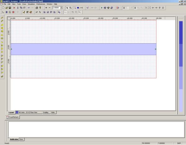
To draw the Linear Waveguide, perform the following procedure. Step Action 1 From the Draw menu, select Linear Waveguide. 2 Draw the waveguide in the center of the wafer and covering the length of the wafer (see Figure 8). Figure 8: Draw Linear Waveguide Inserting the Input Plane To insert the Input Plane, perform the following…
Creating the Script
To create the script, perform the following procedure. Step Action 1 Click the Scripting tab and type the following script: ‘ Change the 2D refractive index StartValue = 1.47 EndValue = 1.5 ‘ RIofWaveguide is the name representing the material ‘ to be manipulated. It can be any other name. Dim RIofWaveguide ‘ Here, “Guide”…
Running the Simulation
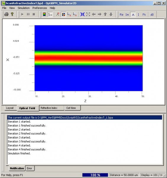
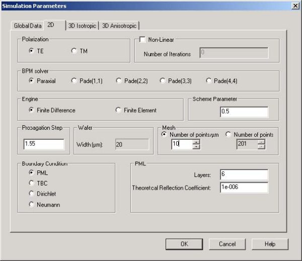
To run the simulation, perform the following procedure. Step Action 1 Save the project as a *.bpd file. 2 From the Simulation menu, select Calculate 2D Isotropic Simulation.The Simulation Parameters dialog box appears. 3 To start the simulation, click Run.A message box appears and prompts you to save the project and run the simulation. 4 Click…
Viewing Results in the BPM Analyzer
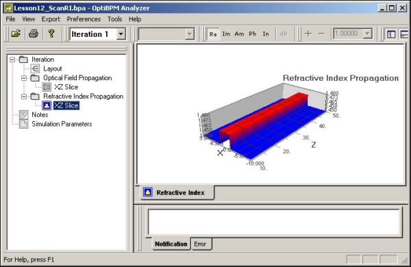
To view the simulation results in OptiBPM_Analyzer, perform the following procedure. Step Action 1 In the OptiBPM_Analyzer project directory, double-click Optical Field Propagation and Refractive Index Propagation. 2 Under Refractive Index Propagation , click XZ Slice. The graph appears in the main layout (see Figure 14). Figure 14: Refractive Propagation Index—XZ Slice 3 In the Iteration…
Introduction
This lesson describes how to define user-defined diffused profiles. In some instances, the predefined diffused profiles available in OptiBPM may not satisfy your requirements. For example, you may want to introduce additional parameters into the equation for a refractive index, or introduce additional dependencies into existing parameters. This lesson details how to create a user-…
Developing the User Defined Profile
As in every project, we start with creating materials of the wafer. Assume Lithium Niobate substrate and air cladding: Step Action 1 From the File menu, select New. The Initial Properties dialog box appears. 2 Click Profiles And Materials. The Profile Designer opens. 3 Under OptiBPM Designer 1, in the Materials folder, right-click the Dielectric folder…
User Defined Profile

Based on the information found in the Technical Background, the extraordinary refractive index, ne , of Ti:Lithium Niobate diffused waveguide have the following profile: The symbols, variables, and functions are explained in Table 9, Table 10, and in the Technical Background. As the equation for refractive index is exceedingly long, we rewrite the equation with…
Create an MMI star coupler
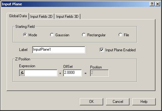
Now that you have completed Lessons 1, 2, and 3, you are familiar with the basic procedures to create projects using OptiBPM: Creating materials Inserting waveguides and input planes Editing waveguide and input plane properties Running a simulation Viewing results and various numerical tools in OptiBPM_Analyzer Lesson 4 and all proceeding lessons provide a high-level…
Create a Chip-to-fiber Butt Coupler
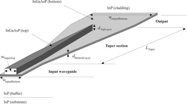
This lesson describes how to create a chip-to-fiber coupler. You will create a model of a simple spot-size transformer based on lateral tapering, as reported in [1]. Highly efficient chip-to-fiber coupling with large alignment tolerances is important for applications of optoelectronic integrated semiconductor devices. Such coupling requires a low-loss change of the light beam spot…
Electro-Optic Modulator
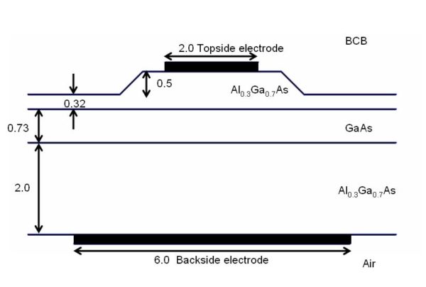
This lesson shows how to make a 3D simulation in a material modified by the linear electro-optic effect (Pockels Effect). The waveguide design of Reference [1] is shown in Figure 1 below. In this lesson, this waveguide is created, a potential is applied to the electrodes, and the results are compared to Reference [1]. Figure…
Integrated Optical Circuit Simulation Using OptiBPM and OptiSystem – Scattering Data Export
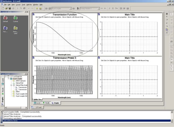
Scattering data is a new simulation feature in OptiBPM. OptiBPM uses scattering data when a small part of a larger photonic circuit is isolated for characterization using BPM. This smaller part has waveguides entering on the left side and exiting on the right side. The N inputs and the M outputs are assumed to have…
Mach-Zehnder Interferometer Switch
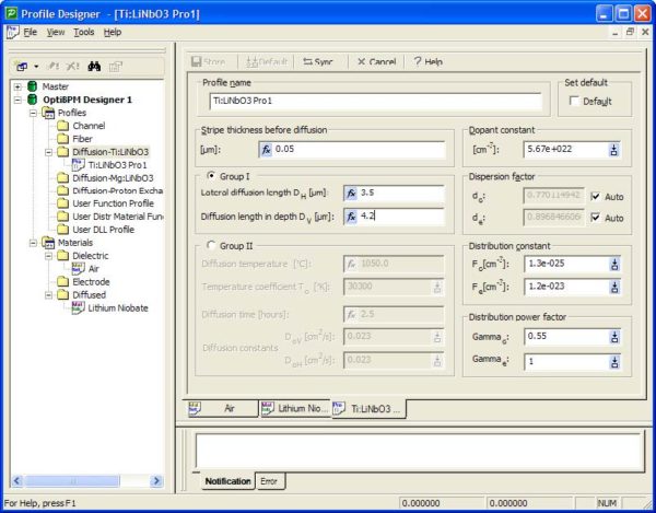
This lesson outlines the design process of an electro-optic 2×2 switch based on integrated Mach-Zehnder interferometer. An electro-optic switch is a device used in integrated fibre optics. The device is based on Mach-Zehnder interferometer made by Titanium diffusion in Lithium Niobate substrate. The switching between the ports is achieved by an electro-optic effect within such…

