
Overview
Plasmonic nano-hole arrays are an interesting avenue of research because of their highly sensitive transmission properties. Incorporating the already strong light-matter interaction of surface plasmons into a periodic structure allows an even greater control over the resonant peaks of the transmission spectra. Like any periodic structure the physical device can be studied effectively by limiting the scope to a single unit cell. Using OptiFDTD, the spectral response of such structures can be investigated in great detail.
Applications
- – Light diffraction in periodic geometries
- – Extraordinary optical transmissions
- – Plasmonic sensors
- – Bio-photonics
- – Sub-wavelength optics
Benefits
- – The periodic structure can be simplified to a single unit cell, allowing the fast simulation of physically large structures.
- – Control over the input field direction can probe the spectral response’s dependence on angle.
- – Ability to explore various diffraction devices
- – Scripting the shape of each unit cell accelerates the design process, allowing multiple geometries to be simulated from the same project.
- – Time domain simulation gives the spectral response of the device from one simulation iteration.
Simulation Description
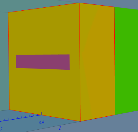
The extraordinary transmission properties of a rectangular air hole plasmonic array was investigated by simulating the unit cell of the periodic structure. Using periodic boundary conditions (PBCs) the simulation domain can be reduced many times its original size, as seen in figure 1. When the input signal is set to a Gaussian Modulated Continuous Wave (GMCW) mode, the finite difference time domain (FDTD) method allows the spectral response to be calculated from one simulation.
Optical designers are interested in the behaviour of a device with respect to one or two parameters, these parameters may control the geometry or material properties in complex ways, which can make manually changing the design file tedious. In these cases, the user is given the option to script the layout. For example, in the current application the orientation angle of air hole φ and the unequal scaling factor θ. The unequal scaling factor relates the lengths of the sides, so a square would have a φ of 45°.
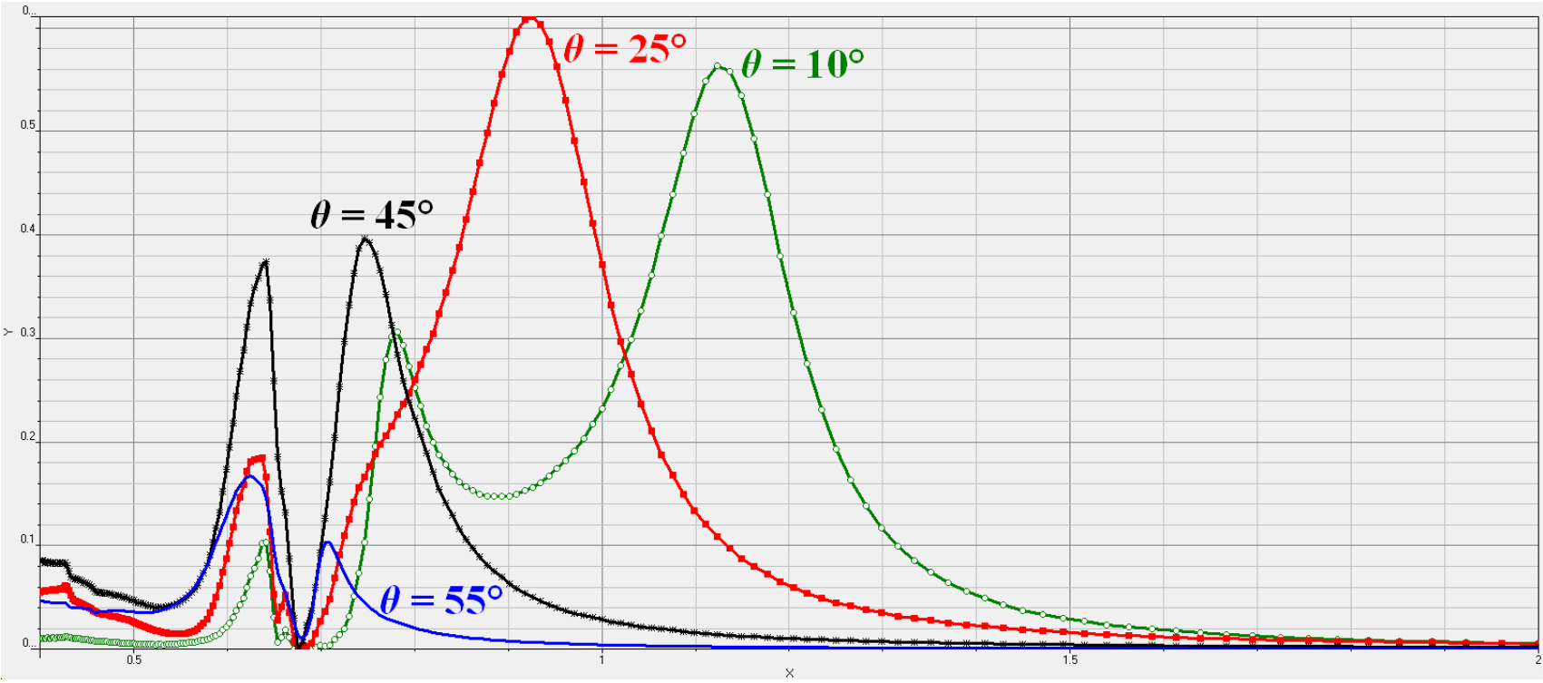
After simulation the wavelength dependence of the transmission is plotted for unit cells with difference aspect ratios, in figure 2. It is found that increasing the aspect ratio, making the rectangle thinner, pushes the secondary transmission peak to larger wavelengths. The peak moves from 0.75 microns to 1.2 microns when the shape is changed from a square to a shape given in figure 1.
The dependence on orientation angle was investigated as well. From figure 3 it is evident that orienting the rectangular cell of figure 1 with the vertical direction reduces the overall transmission. It is important to note the the input light is also polarized along this vertical direction.
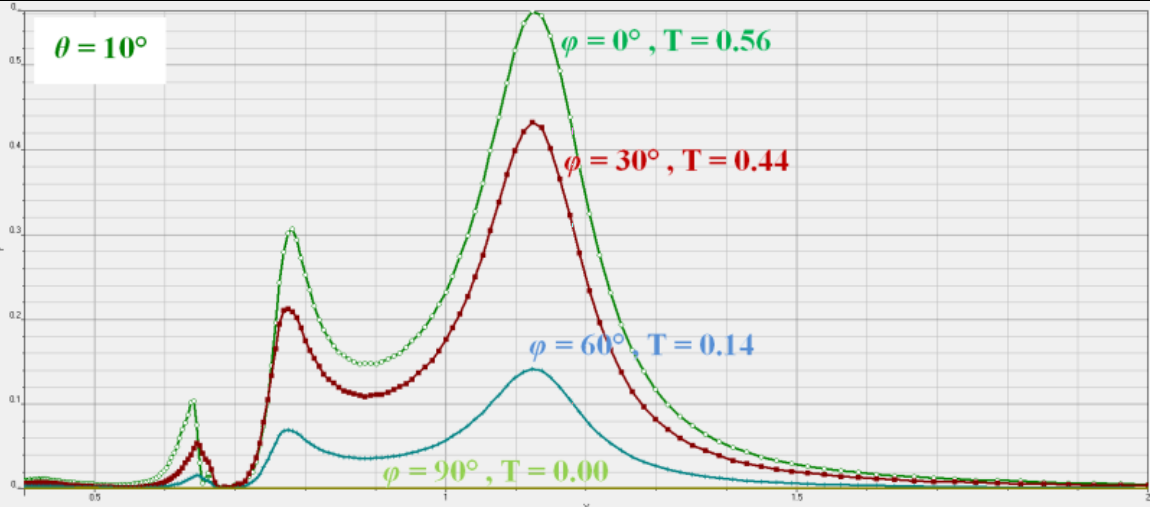
Further experiments with rotating square-like air holes demonstrated that they lack this strong dependence on orientation, because of their symmetricity.