Applications
- High speed internet
- Broadband multimedia access
- Tele-medicine
- Distant learning
Benefits
- Multi-parameter scanning enables system designers to study trade-offs with respect to parameters of interest and to choose optimal designs for deployments.
- Enables users to analyze different algorithms for electronic equalization.
- New BER Test Set enables simulation of milions of bits for direct error counting.
- FEC
- Interfaces with popular design tools.
- Significantly reduces product development costs and boosts productivity through a comprehensive design environment to help plan, test, and simulate optical links in the transmission layer of modern optical networks.
Simulation Description
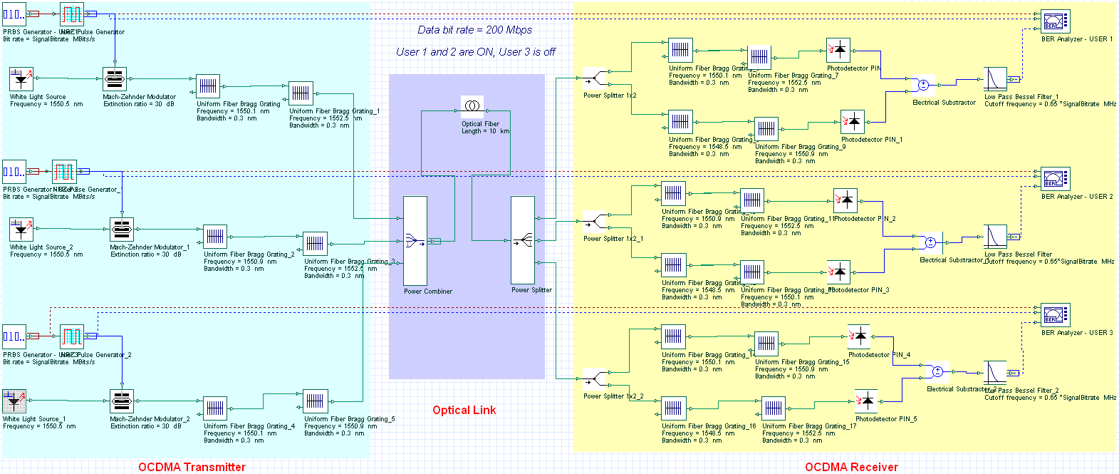
In the above layout, we have simulated a 3-user fiber bragg grating (FBG) based OCDMA network at 200 Mbit/s. Uniform FBGs are used to impelement the Modified Quadratic Congruence (MQC) codes by spectral amplitude encoding. The signal is generated using an incoherent source modulated with NRZ PRBS data using a Mach-Zehnder Modulator. The optical link is 10 km of single mode fiber. The receiver is comprised of two spectral filters and two photodetectors connected in a balanced configuration which perform the decoding with a low-pass filter and a BER analyzer. In this experiment User 1 and 2 are ON and User 3 is OFF.
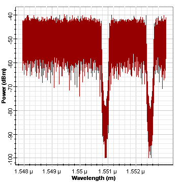
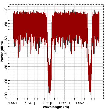
The next two figures demonstrate the spectra of the encoded data for User 1 and 2.
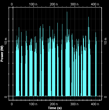
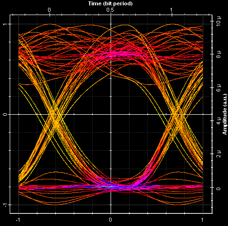
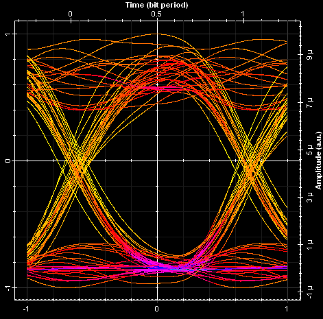
Next we illustrate the signal in time domain for User 1 and eye diagrams for User 1 and 2. Using OptiSystem you can analyze the performance of optical access networks by varying coding schemes, modulation format, number of users, and propagation length.


