
- This topic has 65 replies, 5 voices, and was last updated 8 years, 8 months ago by
Damian Marek.
-
AuthorPosts
-
-
August 3, 2015 at 1:24 am #23004
 cheeParticipant
i want to simulate an OFDM coherent detection system. the system is derived from the sample file from optisystem named Direct Detection Optical OFDM System. however, i have a few warnings at the receiver part. can anyone help me check what is the problem? the file is attached below.
Attachments:
-
August 3, 2015 at 11:54 pm #23035cheeParticipant
i am using optisystem 12.0. please help me as i cannot find out what is wrong..
-
August 4, 2015 at 12:18 am #23038
 alistuParticipant
Hi Chee, You have stated you are faced with some warnings when you run the simulation, while when I run the file it gets interrupted by some error and I am forced to close Optisystem. And I am using Optisystem version 13.0.3. Can you please specify the warnings that you mentioned you receive whenever you run the simulation?
-
August 4, 2015 at 12:37 am #23039cheeParticipant
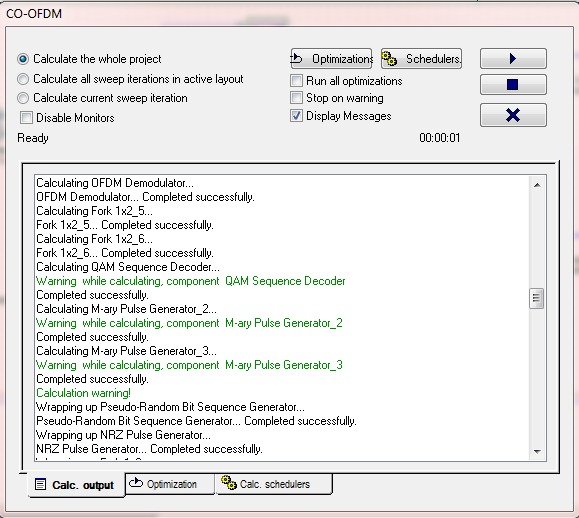
Hi alistu, i attached a PNG file showing the calculation window. i copy this system 100% from an paper i read. but somehow it cannot get the same result. below i attach together the paper that i read.
-
August 4, 2015 at 1:09 am #23040alistuParticipant
I can see no attachments in your reply. By the way, I think you are going to have to convert the PNG file to JPEG to be able to attach it here. I am waiting for your attachments.
-
August 4, 2015 at 1:15 am #23041cheeParticipant
sorry about that and thanks for the tip. here is the file
Attachments:
-
August 4, 2015 at 1:37 am #23044alistuParticipant
Thank. I will try to find the problem as far as my experience with optisystem allows me. By the way, why don’t you use Optisystem’s sample coherent optical OFDM osd file which is located in the “Optisystem Samples” folder? If you have implemented the same system as what you have seen in the papers, then you can use that instead of your own implementation.
-
August 4, 2015 at 1:40 am #23045cheeParticipant
thank you in advanced. because this system is from a paper i read. i was trying to emulate the simulation result first then change it to suit my project. but i will look into that sample to see if it is suitable for my project.
-
August 4, 2015 at 2:09 am #23054alistuParticipant
you are welcome! If I were you, I would have used the sampled OFDM osd file and would have made the necessary adjustments in that. By the way, in case you have not used the optisystem sample files yet, to use them, you would have to install them first. I have been checking your file but have not found the problem yet.
-
August 4, 2015 at 2:13 am #23055cheeParticipant
i just tried the sample file and found that it is exactly same as the system used in the paper. and i have no warnings during calculation. so i will just modify on the sample file. thank you for your time and advice. save me a lot of time.
-
August 4, 2015 at 2:22 am #23057alistuParticipant
You’re welcome, Chee! I think the coherent optical OFDM system implemented in Optisystem samples is based on William Shieh’s CO-OFDM article, which was the first. Some forum members here and I have also worked with optical OFDM systems, so fell free to ask for help if you ever run into any problems.
-
August 4, 2015 at 2:25 am #23058cheeParticipant
i will alistu. thanks a lot for your time.
-
-
-
August 16, 2015 at 1:02 am #23663cheeParticipant
Hello everyone, i am using the sample CO-OFDM provided. the only change i made is using FSO instead of fiber. However, i am not able to get BER value. is there any problem here?
Attachments:
-
August 16, 2015 at 1:39 am #23665alistuParticipant
Hi Chee, First of all, it is advised to use BER test set instead of BER analyzer in OFDM systems. That’s what I have done in the file attached. Look how I have changed some parameters in BER test set to match those of the OFDM components. Aside from this, we have a clear constellation diagram, which shows we have good results.
Cheers!
-
August 16, 2015 at 1:47 am #23667cheeParticipant
Hi alistu, i’m not able to open the file that u attached. it’s said unable to load document from storage. i wonder what is the problem.
-
August 16, 2015 at 2:09 am #23668alistuParticipant
You are using an older version of Optisystem than I do and that’s the reason. But it’s no problem, I have already shown how to use BER Test Set in the forum below:
Also you can emulate what has been done in reply #23260 attached file to replace BER Analyzer with BER test set. Then use OFDM block characteristics for BER test set parameters to get the right BER.
-
August 16, 2015 at 9:29 am #23682cheeParticipant
hello alistu, i am not able to open the file attached in that discussion either. can you teach me where should i connect the BER test set and which component should i remove? i notice in your suggestion in that discussion that the BER test set is connected in serial with the system? and NRZ pulse generator will not be needed?
-
August 16, 2015 at 10:24 am #23683alistuParticipant
Hi Chee, In order to use BER Test Set, please do the following: Firstly delete your PRBS generator, the fork next to it (Fork1x2_1), BER analyzer and the two other components it is attached to. Then Choose BER analyzer from Test Set library and connect its input to the output of QAM decoder and its output to your QAM generator. And that’s it.
-
August 17, 2015 at 12:15 am #23690cheeParticipant
can i know where is the test set library? i only have electrical filter analyzer and s parameter extractor in my test set folder. the folder is located in Default/Visualizer library/electrical/test set. i am using version 12.
-
August 17, 2015 at 1:03 am #23691alistuParticipant
BER Test Set is located in Test Set library in “Binary” folder. I have been using version 13 and if the binary folder is not there in the library in version 12, then it means it has been included in version 13.
-
August 17, 2015 at 1:24 am #23694cheeParticipant
i have found it. However, if i were to delete the PRBS generator, does this mean the BER test set will generate the signal for me instead?
-
August 17, 2015 at 1:30 am #23699alistuParticipant
Indeed!
-
-
August 17, 2015 at 1:28 am #23696cheeParticipant
i have made the adjustment as you said and the value of BER seems too big.
Attachments:
-
August 17, 2015 at 1:35 am #23701alistuParticipant
You need to match the BER Test Set characteristics to those of the OFDM blocks. Double click on the component and tick the “Using OFDM” value in the opened box. Now enter the OFDM related parameters values according to the values you have used for them in your OFDM components and that’s it.
-
August 17, 2015 at 1:43 am #23702cheeParticipant
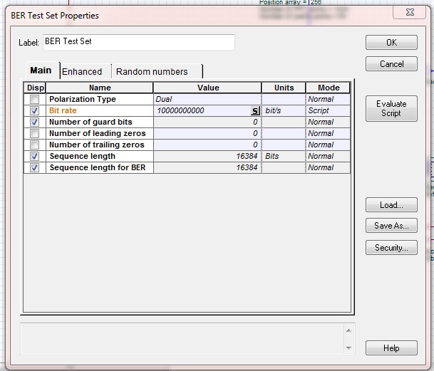
sorry but i couldn’t find the using OFDM option, this is what i get when i double click the BER test set.
Attachments:
-
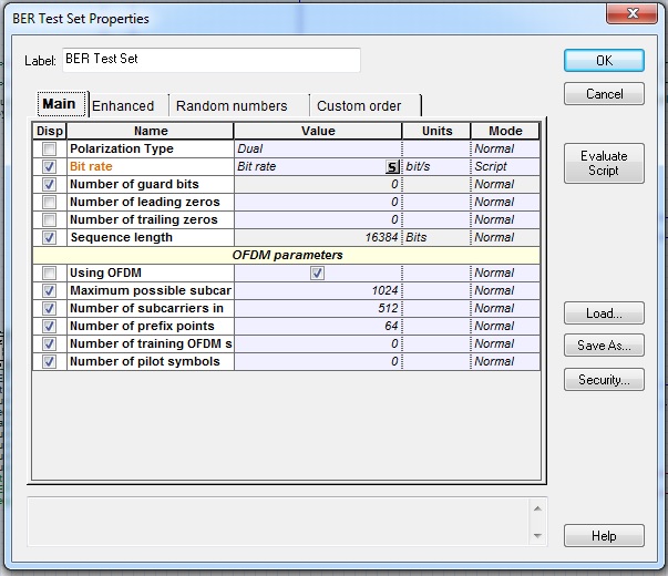
August 17, 2015 at 2:08 am #23705alistuParticipant
Then I’m afraid BER Test Set for Optisystem version 12 does not include that part. But in version 13, as you can see in the screenshot, it is there and filling the parameters according to OFDM components leads to correct calculation of BER.
Attachments:
-
August 17, 2015 at 2:14 am #23708cheeParticipant
so in my case what should i do to be able to measure BER accurately?
-
August 17, 2015 at 2:42 am #23711
 aliParticipant
hi
You will have no problem using version 13
Version 13 to use -
August 17, 2015 at 2:44 am #23712cheeParticipant
but my key is only for version 12…
-
August 17, 2015 at 2:47 am #23714cheeParticipant
is it possible to use version 13 with my key?
-
August 17, 2015 at 2:55 am #23717aliParticipant
i do not have key but do if format hard Problem solved
-
August 17, 2015 at 2:59 am #23719alistuParticipant
You will be able to use optisystem version 13 30-day trial without any keys. The you can go on with a monthly lease if you want the key.
-
August 17, 2015 at 2:49 am #23716alistuParticipant
I Suggest that you use Matlab component to make your own BER measuring block. For this, first you need to go through some basic tutorials on how to work with the component and then using two (or even one) Matlab component, you can measure BER on an empirical basis. Of course, if you are using cyclic prefix, then it gets more complicated.
-
August 17, 2015 at 3:09 am #23720cheeParticipant
i wish to understand the basic about OFDM and both coherent detection and direct detection, such as the effect of changing certain parameter on the OFDM component. but i cannot find related article on the internet. Do you have any source?
-
August 17, 2015 at 3:28 am #23722alistuParticipant
I suggest that you search for “OFDM Tutorial” on google to see the related tutorials and see which one you find easier to start with. This way you choose the one more appropriate for your knowledge of the subject. If I want to introduce one, I’d do the same thing so I’d suggest you do it yourself.
-
August 17, 2015 at 3:38 am #23724cheeParticipant
Thanks Alistu, i already did this and read through the theory part of OFDM. however, these articles didn’t concern about the effect of each parameter like position array, FFT point and prefix points. i am looking for more practically speaking article.
-
August 17, 2015 at 3:56 am #23725alistuParticipant
You’re welcome. Have you taken a look at the help section of the OFDM component itself? Also, Damian explained the same parameters as the ones you want to know a couple of months ago. It’s in the reply #17621 on the link below. I hope this helps.
-
August 17, 2015 at 4:25 am #23727cheeParticipant
Thanks alistu, this has been a great help. i would like to try create BER measuring block using MATLAB, but i have zero knowledge on this matter. can you show me which is the best way to learn?
-
August 17, 2015 at 4:46 am #23728alistuParticipant
You’re welcome. I can refer you to a topic in which Damian has introduced a couple of pdf files and videos that explain the basic fundamentals of the Matlab component and how it can be integrated with Optisystem:
-
-
August 17, 2015 at 9:00 am #23752
Damian Marek
ParticipantHi Chee,
There were some problems with the older OFDM components, but they can be circumvented by copying the type of layout in the reply I made. You need that decision component, because the signal that comes out of the OFDM Demodulation is not correct!
Please try to copy that snapshot!
-
August 18, 2015 at 3:05 am #23778cheeParticipant
Damian, does this mean i need to copy the components after OFDM demodulator? what is inside the subsystem?
-
August 18, 2015 at 3:20 am #23780alistuParticipant
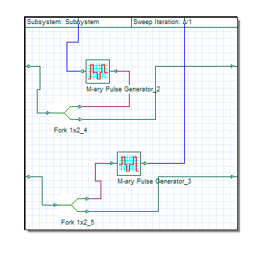
The subsystem is the same as the one there in Optisystem 12 sample CO-OFDM. It is just used for constellation visualizer. And you need to implement the part between OFDM demodulator and QAM decoder. Otherwise the system in Damian’s post uses direct detection technique, unlike your coherent detection case.
-
August 18, 2015 at 4:08 am #23783cheeParticipant
thank you alistu and damian. i am not very clear about the function of M-ary pulse generator and the decision component. can you explain in brief?
-
August 18, 2015 at 6:45 am #23798alistuParticipant
You’re welcome Chee. I believe the Decision component helps with deciding on the received symbols with the help of some procedures like normalizing the input port signals, and since its input should be electrical, we use M-ray pulse generators to convert the M-ary signal from OFDM demodulator to electrical signal.
Cheers!
-
August 18, 2015 at 9:16 am #23807Participant
What I have come to understand is that the old OFDM components would output M-ary signals, which should be discrete levels e.g. -3 -1 1 3. However, the M-ary signals that come out of the OFDM component have more of an electrical signal nature, so something is clearly wrong. If you convert these signals to electrical using the M-Ary Pulse Generator and then reconvert them back to M ary signals the QAM Sequence Decoder will function properly. The Subsystem there is for the display of the constellation and the snapshot is attached.
Attachments:
-
August 19, 2015 at 1:54 am #23820cheeParticipant
thank you Damian and alistu. i have made the changes. but at the decision component, there is only options for either QPSK or 16QAM. i am using 4 QAM, is there any differences? attached is my osd file. please help me check for any mistake.
Attachments:
-
August 19, 2015 at 4:49 am #23836alistuParticipant
Hi Chee, I will check your file the moment I get access to the software. Despite the fundamental differences between the concepts of PSK and QAM, the two modulation schemes QPSK and 4-QAM are exactly the same. So there’s no problem in this regard.
-
August 20, 2015 at 2:44 am #23871cheeParticipant
how do i know the frequencies of each subcarrier ?
-
August 20, 2015 at 2:49 am #23872cheeParticipant
in another case of direct detection OFDM, i not quite understand the function of quadrature modulator after the LP cosine roll off filter.
Attachments:
-
-
-
August 20, 2015 at 2:24 am #23868
 Dhananjay PatelParticipant
Hi Chee,
I have gone through your design “Coherent-Detection-Optical-OFDM-System-TRIAL2.osd”. Please do not use OFDM modulator and demodulator block from optisystem 12. Instead download 13 and trying using them. Besides the attenuation which you have chosen for FSO is very low. (Typicall its 25dB/Km).
-
August 20, 2015 at 2:38 am #23870cheeParticipant
thank you Dhananjay. actually i am weighing up the option of upgrading my 12 license to 13. but i am not sure what is the advantage of OFDM in 13. can you advice me on that matter.
also the attenuation value is not what i am gonna use in my project. my real project would be convert rain rate to attenuation using Matlab then use the attenuation to run simulation. the FSO component block in Optisystem is rather too simple as we can only manipulate the attenuation in fact there are too many aspect that can affect the propagation. i think Optiwave should consider this in future upgrade.-
August 20, 2015 at 3:16 am #23879alistuParticipant
Hi Chee, Optisystem 13 OFDM components have some remarkable advantages over former OFDM components. For one thing, the rotation problem you face using the OS12 components and you were referring to in another forum is solved by employing training and pilot symbols for channel estimation. Also, it has the capability to modulate different carrier ranges with different modulation formats. These features might interest you.
-
August 20, 2015 at 3:40 am #23885cheeParticipant
hi alistu, i tried run simulation of the sample direct detection OFDM 4QAM using Optisystem 13. the constellation diagram at the receiver side is in perfect shape. but the BER i got is 0.5. also i am not sure about the function of the quadrature modulator after the LP cosine roll off filter.
Attachments:
-
August 20, 2015 at 8:43 am #23905Participant
There was a free space optical channel added to your sample file, and since OFDM schemes are very sensitive to noise the signal was too distorted. The quadrature modulator is needed in (I think) most direct detection schemes. It contains an electrical carrier inphase and 90 degrees out of phase to create the correctly modulated signal.
Regards
-
August 21, 2015 at 2:27 am #23918cheeParticipant
Hi Damian, but the constellation diagram on the receiver is identical to transmitter side. shouldn’t this mean the signal is perfectly transmitted?
-
August 21, 2015 at 7:38 am #23925alistuParticipant
Actually I have had the same problem. Is it because the new OFDM demodulator also makes the decision based on the quadrant each symbol is in? In this case, would it be possible in any way to see the constellation as before so as to get an insight about how well the system works (aside from BER)? Thanks Damian.
-
August 21, 2015 at 10:01 am #23940Participant
When you are looking at that particular constellation the OFDM has already demodulated the signal and regenerated the M ary signal, so of course the constellation looks perfect, although many of the symbols have been detected incorrectly. Look at the graphs of the OFDM Demodulation from the Project Browser. In particular there is a graph called Constellation before channel estimation which shows how unclear the constellation really is.
-
-
-
August 24, 2015 at 3:32 am #24002cheeParticipant
i try to recreate my co-ofdm using sample from optisystem13 named OFDM Coherent Detection Single Port Dual Polarization 16QAM. however, i was unable to change the value at the OFDM demodulator and BER test set to the value i want. however, i was able to change it on the OFDM modulator. the maximum subcarrier in the BER test set is stuck at 128. plus i would like to ask about the position of the pilot symbol. will it affect the performance if i change their position? were their position fixed? how do i decide how many pilot symbol i need?
-
August 24, 2015 at 6:26 am #24010alistuParticipant
Hi Chee, Maximum possible subcarrier did not have the same value in both your OFDM components. I set the maximum possible subcarrier equal to the same value for both OFDM components. Then in the BER test set, I unticked “using OFDM” and clicked “OK”. The next time I opened BER test set, I managed to change the value of maximum possible subcarrier after ticking “Using OFDM” box.
-
August 25, 2015 at 1:31 am #24058cheeParticipant
Thank you alistu. after i change the setting on the OFDM and BER test set, the original positions of the 6 pilot symbols become incorrect. i randomly place them inside the range of subcarrier but the simulation turns out to contain error. is there any rule for placing pilot symbol?
-
August 25, 2015 at 2:11 am #24062alistuParticipant
Dear Chee, There is a mistakes in your parameter settings: In OFDM modulators, you have used 512 subcarriers, while you have only chosen the location of 256 of them. I made the change and the simulation was run without error. There is nothing wrong with position of your pilot symbols, since they all are in the interval defined for subcarrier location.
Cheers!
-
August 25, 2015 at 2:22 am #24063cheeParticipant
Dear alistu, i have made the amendment but still there is error in my simulation. i have already placed the subcarriers between 257-768.
-
August 25, 2015 at 3:31 am #24065alistuParticipant
I couldn’t figure out the problem, sorry about that. I will let you know if I manage to solve it.
-
August 25, 2015 at 3:40 am #24066cheeParticipant
thank you alistu. is training symbol same as pilot symbol? in the example, the number of training symbol is set at 10 but only 6 positions defined.
-
August 25, 2015 at 4:01 am #24067alistuParticipant
According to the explanations given in the help section of the OFDM demodulation component, training symbols and pilot symbols are not the same. And in the OFDM settings section of the BER Test Set, you can set both the values of training OFDM symbols and the number of pilot symbols used.
-
-
-
August 26, 2015 at 9:38 am #24114Participant
Hi all,
I am going to close this discussion as it is pretty long and hard to navigate. It also seems the conversation has drifted to a slightly different topic. Chee, if you have more questions please go ahead and post a new Discussion!
Thanks!
-
-
AuthorPosts
- The topic ‘Coherent detection OFDM’ is closed to new replies.