
Introduction
In high speed Digital Signal Processing (DSP), coherent detection technique is used in complex quasi-monochromatic fields modulated Digital Subcarrier Multiplexed (DSCM) systems. Coherent detection is a common phenomenon used in communication systems, where a local carrier mixes with the received radio frequency (RF) signal to generate a product term. As a result, the received RF signal can be frequency translated and demodulated.
The block diagram shown in Fig. 1 demonstrates multiplexing (MUX) and de-multiplexing (De-MUX) of two different frequency channels in the DSCM systems using coherent detection. Digital-to-analog and analog-to-digital signal processing is not shown here. The entire circuit is build and simulated in Tanner S-edit using building blocks from Ligentec PDK foundry and OptiSPICE device library.
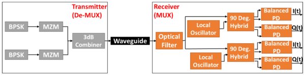
Fig 1. Block diagram of BPSK coherent detection demodulator
OptiSPICE Plugin
- OptiSPICE Tanner plugin is created by Optiwave and Mentor Graphics
- Seamless integration of optical models into the Tanner EDA allows simulation of complex opto-electronic circuits from schematic and mask-layouts within single design environment
- It allows circuit and/or chip level simulations
- Provides a platform for PIC design and simulation
- Device modelling capabilities for global foundries
Supported Features
- Multi channel bidirectional optical time and frequency domain simulation with SPICE
- Opto electronic feedback and control loop simulation
- Noise, channel cross talk and interference effects
- PDK support for Tanner GPIC and other foundries like Ligentec, HHI & CNM
- Optical S-parameter device for passive components
- Compact model creation based on user defined or experimental data
- Optical signal visualization with Tanner waveform viewer
- Seamless workflow allows to create and test either a single device or a fully featured optical chip
Simulation and Results
The transmitter contains two binary phase shift keying (BPSK) signal generators which send two different frequency channels through Mach Zehnder Modulators (MZM). These signals are modulated using the bit generator at a modulation frequency of 100 GHz. These modulated signals are then combined using an optical 3dB-combiner. This transmitted signal passes through a 500um long waveguide (taken from Ligentec PDK), which further goes to an optical filter in the receiver. This optical filter is used to split the channels into two and has a flat-top response which can be seen in Fig. 2. It comprises of three directional couplers and two second order ring filters taken from Ligentec PDK.
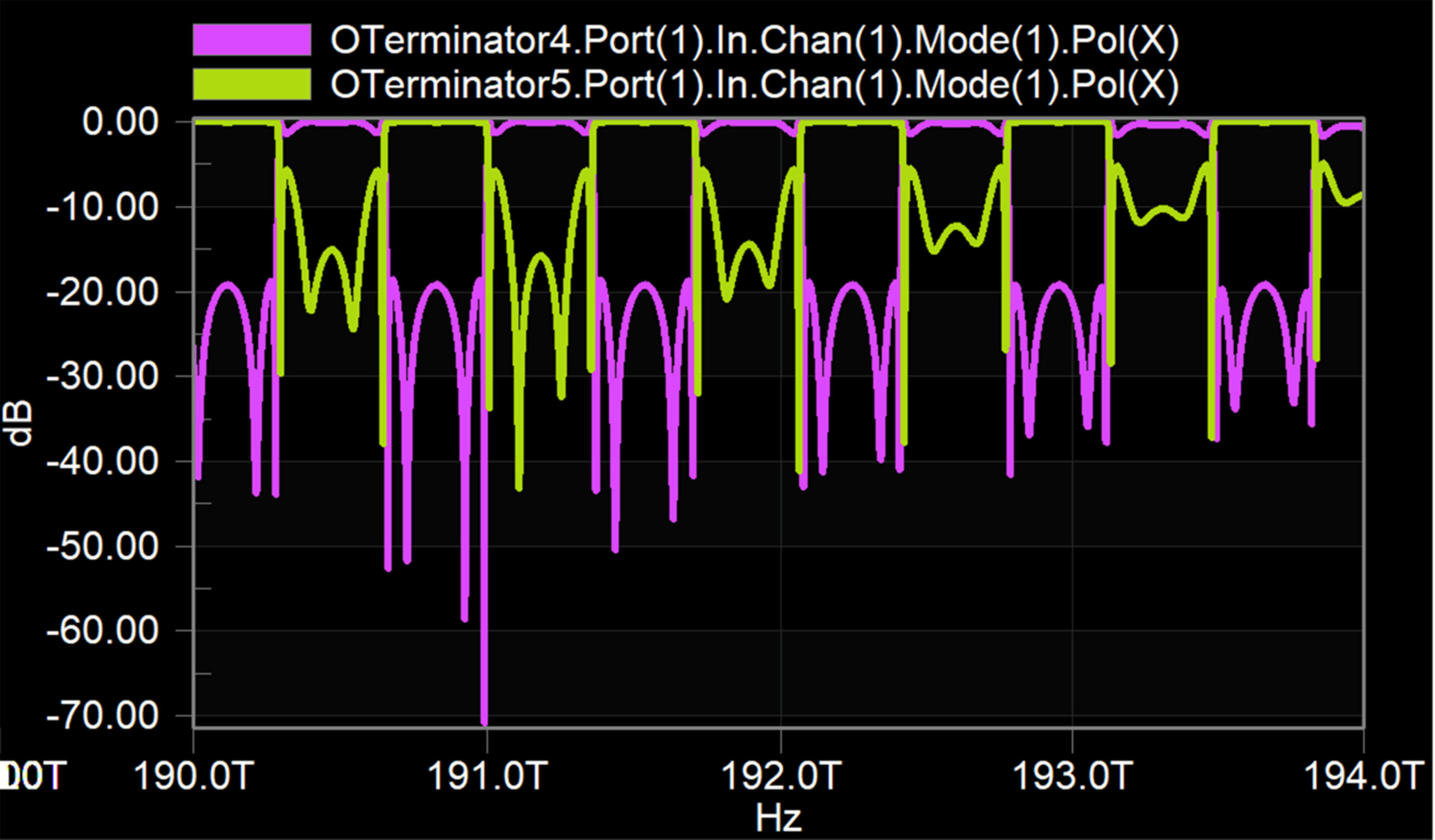
Fig 2. Transmission response of the optical filter
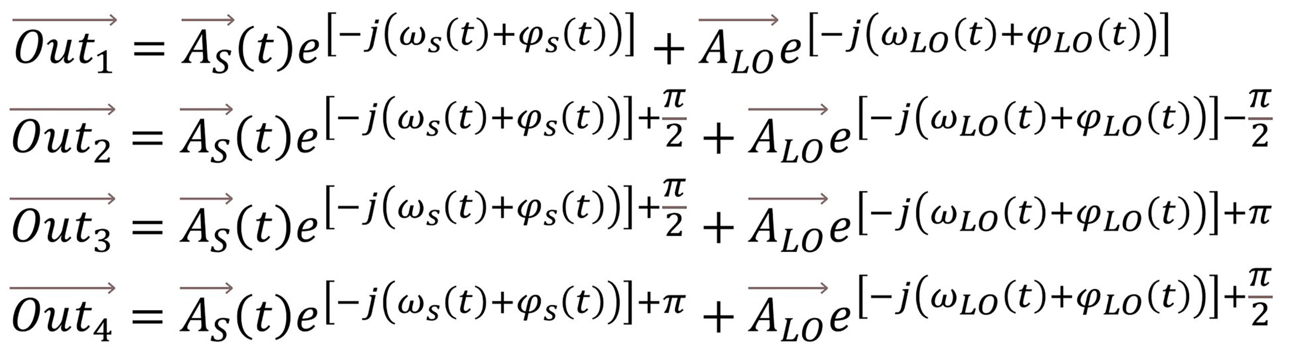
The split signals further enter two 90-degree hybrid devices which mixes the incoming optical field with the local oscillator (LO) optical field and produces four outgoing signals with phase difference of 0, π, 3π/2 and π/2. The signals going out of 90-degree hybrid can be expressed using the following equations:
Considering ideal homodyne balanced detection, we obtain the in-phase component [I(t)] and the quadrature component [Q(t)] of the detected BPSK signals which is shown in Fig. 3 for two different frequency channels. The plot above is for the frequency channel 1 (190.8241 THz) and the plot below for frequency channel 2 (191.5291 THz). The I(t) signals are around 16mV, whereas, Q(t) signals are in nV range (almost 0).
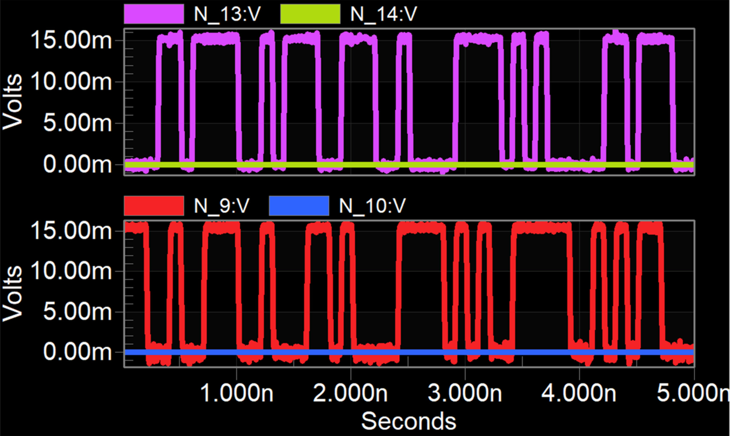
Fig. 3 Plot showing the In-phase component [I(t)] (N_13 & N_9 signal) and Quadrature component [Q(t)] (N_14 & N_10 signal) of two different BPSK frequency channels.
Please click the below links to download our application note and presentation.
Application Example Using Ligentec PDK