
The large-signal characteristics are related to the digital on/off switching of the laser diode. First, we will demonstrate the delay time required to achieve the population inversion to produce the gain. Second, we will demonstrate the typical for the direct modulation of semiconductor laser amplitude and phase modulations.
For the laser which is completely turned off, the carrier lifetime will limit the modulation rate. For a current pulse Ip , a period of time td given by:
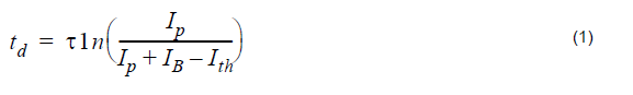
is needed to achieve the population inversion to produce a gain. IB and Ith are the bias and threshold currents, and T the average lifetime of the carriers. From this formula could be inferred that the time delay can be eliminated by biasing the diode at the lasing threshold current.
We will demonstrate this dependence in Figure 1.

Figure 1: Project layout
Discussion of the numerical parameters: bit rate is 1 Gb/s and sequence length 8 bits, therefore, the time window is 8 ns. Samples per bit are 512, therefore, the sample rate is about 500 GHz. The default resolution therefore is about 120 MHz.
In Figure 2, the initial electrical pulse is shown.

Figure 2: Initial electrical pulse
while in the next two figures are shown generated optical pulses with modulation peak
power current I = 50mA . In the graph on the left of Figure 3, IB = 10mA , which
is below the default value of Ith = 33.46mA , and in the graph on the right, IB = Ith = 10mA. In the case IB = 10mA , td according to the above formula will be about 0.6 ns, when we have taken T = Tsp .

Figure 3: Generated optical pulses
When we compare the generated optical pulse from the graph on the left with the
electric pulse, we can see the time delay in the appearance of the optical pulse ,
which is approximately 0.6 ns. If we compare the generated optical pulse from the
graph on the right with the electric pulse, we see the time delay tD is about 0. In both
cases good agreement with the predictions of the previously discussed formula can
be seen.
Another basic property of the directly modulated lasers is the amplitude and phase modulation of generated optical pulses. The characteristic amplitude modulation is well demonstrated in Figure 4. Pulses with a phase modulation are also described as chirped. In what follows, we will demonstrate both the amplitude and the phase modulations. Two kinds of chirps are distinguished: adiabatic and transient.
The adiabatic chirp can be observed when the “off” state level is nonzero and it is dominant at low frequencies.
For the case of 1 Gb/s (modulation peak power current I = 50mA), we will
demonstrate the appearance of the adiabatic chirp as a function from the IB. In the
next two figures, we will see the amplitude and phase modulation (chirps) for the case
of IB = 30 and 40mA, respectively.

Figure 4: Adiabatic chirp
It is clear to see the nonzero off state in the second case and correspondingly, the appearance of the adiabatic chirp.
With Figure 5, we will demonstrate the disappearance of the adiabatic chirp for larger frequencies, – 5 Gb/s transmission, keeping all other parameters the same.

Figure 5: Adiabatic chirp disappearance
Obviously very different amplitude and phase modulations can be seen. The adiabatic chirp disappears.
The transient chirp is associated with the time rate of change of the optical power. The rate of the change is greatest at the leading edge of the pulse when the bias current is below the threshold current.
In the next two figures the amplitude fluctuations and the corresponding transient chirps will be compared for the case of 1 Cb/s transmission with IB = 20 and 40mA. In the first case, much greater transient chirp is expected.

Figure 6: Transient adiabatic chirp
Qualitatively different behavior of both amplitude and phase modulations can be seen. Note the much larger transient chirp in the first figure.
The large-signal characteristics of directly modulated semiconductor lasers were demonstrated. The delay time required to achieve the population inversion to produce the gain and typical amplitude and phase modulations were shown.
References:
[1]G.P. Agrawal, Fiber-Optic Communication Systems, John Wiley & Sons, Inc, second edition, 1997.
[2]G. Keiser, Optical Fiber Communications, McGraw-Hill Higher Education, third edition, 2000.
[3]B.W. Hakki, “Evaluation of transmission characteristics of chirped DFB lasers in dispersive optical fiber”, Journal of Lightwave Technology, vol.10, pp.964-970, 1992.