
File: New > Waveguide Coupler
The Waveguide Coupler Module
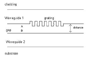
You use the Waveguide Coupler Module to model a two slab waveguide with a
grating. The grating can be placed on the interface of layers as surface relief grating,
or in layers as indexmodulated grating.
You can simulate the coupling between modes of the two waveguides. There are two
mode options available: TE or TM modes of the waveguide. The Waveguide Coupler
finds applications in waveguide co-directional and contra-directional couplers, direct
and exchange waveguide Bragg reflectors, and in filters.
The Waveguide Coupler Profile dialog box
In the Waveguide Coupler dialog box, you enter the main data concerning the
waveguide coupler dimensions, index profile, and photosensitive profile.
To open the Waveguide Coupler dialog box
| 1 | File > New. |
| 2 | In the New dialog box, click Waveguide Coupler. |
| 3 | In the Project window, click the Fiber/Waveguide Parameters button. |
| 4 | In the Waveguide Coupler dialog box, you can define the following options: |
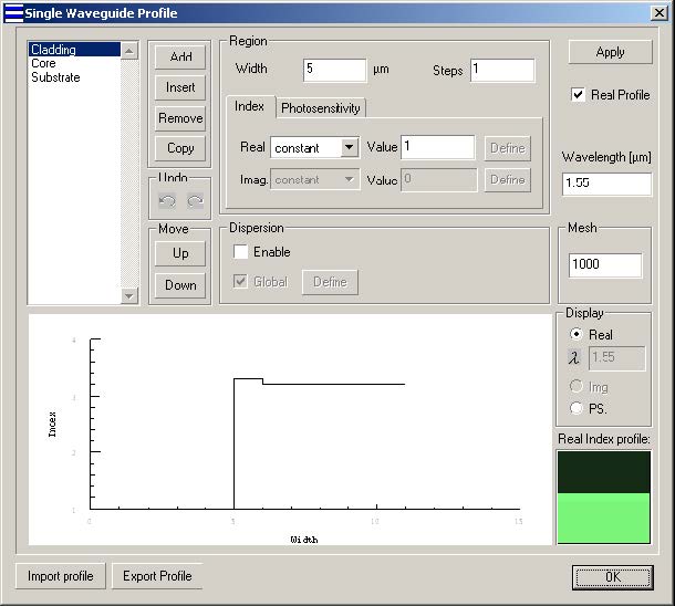
Waveguide 1
Select Waveguide 1 button to define the profile of waveguide 1. The options for
waveguide 1 are same as Single Waveguide profile (see Single Waveguide Profile
dialog box).
Waveguide 2
Select Waveguide 2 button to define the profile of waveguide 2. The options for
waveguide 2 are same as Single Waveguide profile (see Single Waveguide Profile
dialog box).
Distance
Distance is the width of the common cladding of the coupler.
Note: To make sure the waveguide coupler has common cladding, The last
region of Waveguide 1 (Point A) and the first region of Waveguide 2 (Point B)
should be defined by constant real index profile with Steps equal to 1 with same
index value. The width of the last region and the first region of Waveguide 2 are
not important, as the sum of these widths is replaced by Distance.
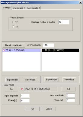
Waveguide Coupler Modes dialog box
After you have finished the data entry in the Waveguide Coupler profile dialog box,
OptiGrating computes two lists of guided modes, which are displayed in the
Waveguide Coupler Modes dialog box. You can select one Waveguide 1 mode and
one Waveguide 2 mode.
The options in the Waveguide Coupler Modes dialog box are similar to the ones in the
Sin-Waveguide Modes dialog box.
To compute waveguide coupler modes
| 1 | File > New. |
| 2 | New > Waveguide Coupler. |
| 3 | In the Project window, click the Fiber/Waveguide parameters button. |
| 4 | In the Waveguide Coupler Profile dialog box, enter the desired values and click the OK button. |
| 5 | In the Waveguide Coupler Modes Settings tab, select one mode from the Waveguide 1 Modes list and one mode from the Waveguide 2 Modes list. |
| 6 | In the Waveguide 1 and Waveguide 2 Amplitude boxes, enter the desired values. |
| 7 | In the Phase boxes for Waveguide 1 and Waveguide 2, enter the desired values. |
| 8 | Choose either the Waveguide 1 or Waveguide 2 tab, to get the following options: |
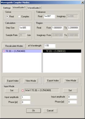
- Similar to the Advanced Settings option in Single Fiber Modes, choosing either
the Real or Complex button in the Solver box will determine which variables you
may change.
In the Real option, real solutions will be sought in the interval specified in the Real
From and To fields. The solver will step through this interval in steps of Step Size.
In the Complex option, solutions are sought in a rectangular region of the complex
plane as defined by the From and To fields in both real and imaginary. The Complex
option uses an advanced technique for finding the roots as described in the Technical
Background chapter of the OptiGrating manual.
| 9 | Click OK. |
Using Calculation Options
The calculation options are similar to the ones described in Single Fiber calculation
section.