In this lesson we show an example of the synthesis of a filter with an arbitrary user
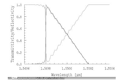
defined spectrum. In this example, we ask for a bandpass filter having a reflection
coefficient with a linear variation of amplitude (the reflectivity has a square root
variation).
Step 1
| 1 | Choose File > New > Single Fiber. |
| 2 | Then select Calculation > Inverse Scattering Solver, to get Inverse Problem Solver dialog box. |
| 3 | In the Inverse Problem Solver box, make sure the User-Defined checkbox is checked. |
| 4 | Enter the starting and ending wavelengths, and the number of Steps in the User-Defined frame as shown. |
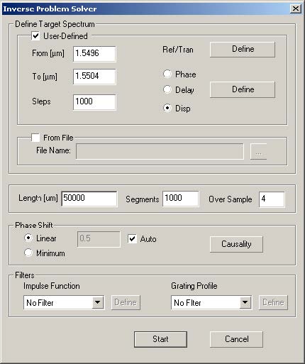
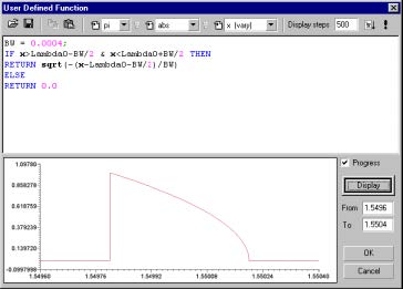
| 5 | Click on the Define button next to the Ref/Tran and enter the formula shown below to define the reflectivity. |
| 6 | Click OK. |
| 7 | Select the Disp button. |
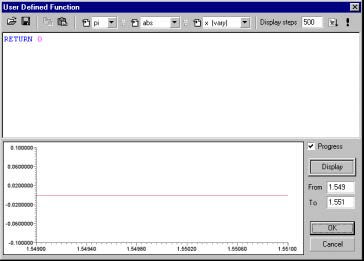
| 8 | Click on the adjacent Define button to define the dispersion. |
| 9 | Click OK. |
Step 2
| 1 | Click on Start to reconstruct the grating. |
| 2 | Select the Power tab at the bottom of the screen to see the reflected and transmitted power. |
| 3 | Right click the mouse in the graph window to pull down the menu and select Axis Properties. |
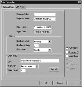
| 4 | Select the Left Y axis and uncheck the Show in dB box to show the reflection in a linear scale. |
| 5 | Click OK. |