
File: New > Single Waveguide
The Single Waveguide Module
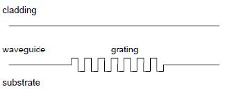
You use the Single Waveguide to model a multilayer slab waveguide with grating. The
grating can be placed on the interface of layers as surface relief grating, or in layers
as index-modulated grating.
You can simulate the coupling between forward and backward propagating modes.
There are two mode options available: TE or TM modes of the waveguide. The Single
Waveguide module finds applications in thin-film optical filters, distributed feedback
lasers (DFB), distributed Bragg reflector lasers (DBR), and waveguide Bragg
reflectors.
To select the Single Waveguide module
| 1 | File > New. |
| 2 | In the New dialog box, click Single Waveguide. |
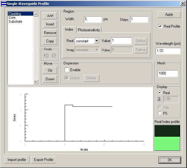
The Single Waveguide Profile dialog box
In this dialog box, you enter the main data concerning the single waveguide
dimensions, index profile, and photosensitive profile.
To open the Single Waveguide dialog box
| 1 | In the Gratings box, click the Fiber/Waveguide Parameters button. |
| 2 | In the Single Waveguide dialog box, you can define the following options: |
Photosensitivity
Type: Select one of the following options for the radial photosensitivity profile within
the current region:
Constant – Constant value of radial photosensitivity
Linear
Parabolic
Gaussian
Exponential
Alpha-peak
Alpha-dip
User Function – Functional dependence of the sensitivity, where the function is
defined or programmed using the powerful Script Language environment.
Value: Numerical data entry box – Present when the constant radial photosensitivity
option was selected. Enter the radial photosensitivity value for the selected region.
Define: Present when the Function or User Function option was selected. Press the
Define button to specify the function. For the built-in functions, a dialog box related to
one of the predefined functions appears. For the User Function option, pressing the
Define button launches the User Defined Function script-programming environment.
Note: The surface-relief grating will be located at the top of the region when the
photosensitivity of this region is not equal to zero. The gratings can only be
located at one waveguide interface. If more than one region is photosensitive, the
grating will be located at the first region (in the region list). The definitions of other
photosensitivity will be ignored.
Mesh: Number of points in the transverse cross-section along Y-axis
The definitions of the other Options in this dialog box are same as in the Single fiber
profile dialog box.
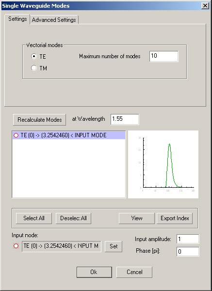
Single Waveguide Modes dialog box
After you have finished the data entry in the Single Waveguide dialog box,
OptiGrating allows you to compute Waveguide modes. The waveguide modes are
listed in the Single Waveguides Modes dialog box. You can select modes for
calculations.
In the single Fiber modes dialog box, you can define the following options:
Vectorial modes
TE – Check this option to calculate the Transverse Electric (TE) modes of waveguide
TM – Check this option to calculate the Transverse Magnetic (TM) modes of
waveguide
View
View and export the modal fields. See 2D Preview of the field dialog box.
Recalculate Modes
Press this button to start calculate modes
Select All
Select all the modes from the mode list
Deselect All
Deselect all the modes from the mode list
Set
Set the current selected mode as input mode
Input amplitude
The amplitude of the selected input mode
Phase
The phase of the selected input mode
Export Index
Export the effective refractive index to a text file.
To compute guided modes in the Single Waveguide Modes dialog box
| 1 | File > New. |
| 2 | In the New dialog box, click Single Waveguide. |
| 3 | In the Gratings box, click the Fiber/Waveguide Parameters button. |
| 4 | In the Single Waveguide dialog box, enter the desired values and press the OK button. |
| 5 | In the Single Waveguide Modes dialog box, select modes from the list. |
| 6 | In the Input Amplitude and Phase boxes, enter the desired values. |
| 7 | Choose the Advanced Settings Tab. |
| 8 | In the Advanced Settings dialog box, choose either Real or Complex in the Solver box to enter the desired values and press OK. |
By selecting the Advanced Tab in the Single Waveguide Modes window, you will see
the following choices:
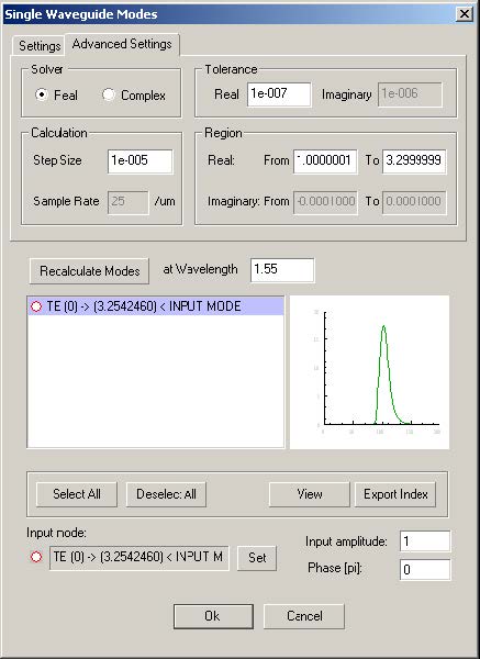
- Similar to the Advanced Settings option in Single Fiber Modes, choosing either
the Real or Complex button in the Solver box will determine which variables you
may change.
In the Real option, real solutions will be sought in the interval specified in the Real
From and To fields. The solver will step through this interval in steps of Step Size.
In the Complex option, solutions are sought in a rectangular region of the complex
plane as defined by the From and To fields in both real and imaginary. The Complex
option uses an advanced technique for finding the roots as described in the Technical
Background chapter of the OptiGrating manual.
2D Preview of the field dialog box
To Access the 2D Preview of the field dialog box:
| 1 | Follow steps 1 to 5 from the “To compute guided modes” procedure in Single Waveguide Modes dialog box section. |
| 2 | Press the view button in the Single Waveguide Modes dialog box. |
Note: You can also access this dialog box from Waveguide Coupler Modes dialog
box.
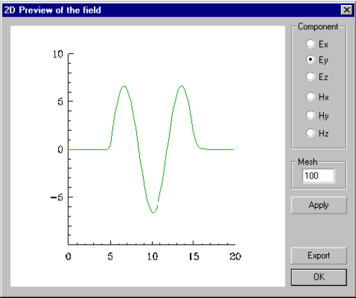
The Properties of the dialog box options are described below.
Component
Enable one of the component buttons: Ex, Ey, Ez, Hx, Hy, Hz. The enabled field
component will be displayed and exported.
Mesh
Number of points in the transverse cross-section along Y-axis
Apply
Apply the changes made in the dialog box.
Export
Export the modal field. The file format is the field *.f2d of BPM_CAD. The exported 2D
Complex Format:
2D complex format:
BCF2DCX – File Header
N – Number Of Data Points
W – Mesh Width (μm)
Z1 – First Complex Data Point
Z2 – Second Complex Data Point
.
.
.
ZN – Last Complex Data Point
Using Calculation Options
The calculation options are similar to the ones described in the Single Fiber
calculation section.