
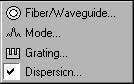
The Parameters menu gives you access to all grating parameters: Fiber/Waveguide,
Mode, Grating, Dispersion.
Fiber/Waveguide
Depending on which module you calculate, the Fiber/Waveguide command gives you
the basic parameters about fiber or waveguide profile, including refractive index
profile, Photosensitivity profile.
Mode
Shows a list of supported modes for entered Fiber/Waveguide Parameters.
Grating
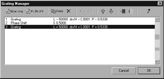
Opens the Grating Manager. In the Grating Manager dialog box, you add gratings,
phase shifts, and change data.
Dispersion
The material and waveguide dispersion are included for the selected calculation.
Grating Manager
File: New > Module option > Parameters: Grating
The Grating Manager
The Grating Manager allows you to define the grating structure as a collection of
gratings.
To open the Grating Manager
| 1 | Parameters > Grating. |
Note: You can also open the Grating Manager dialog box by clicking the Grating
button in the Grating Manager dialog box.
Working With the Grating Manager
The Grating Manager allows you to perform all of your tasks quickly and effectively by
using the following buttons:
Add Grating or Add Phase Shift
![]()
Those buttons allow you to add an item (a grating or a phase shift) that uses the
default values at the end of the list.
When you click the Grating button in the Grating manager dialog box, and then click
the Edit Item button, the Grating Definition dialog box opens.
When you click the Add Phase Shift button, the Phase Shift dialog box opens, and
you can define the phase shift between the gratings. To do so, enable the Phase
button, click the Edit Item button to open the Phase Shift box, type a value in the
Phase box, and click the OK button.
Copy Selected Items or Delete Selected Items
![]()
Those buttons allow you to copy and delete multiple items from the list.
The copied objects are added at the end of the list and stay selected so that if you
want to copy the same selection of items again, you just have to press the Copy
button. Thus, you can easily create a fiber/waveguide that consists of hundreds of
grating objects. When copying a grating, you have to specify its parameters in the
Grating Definition dialog box.
Use the Delete Selected Items button to delete multiple grating objects, but remember
that there should be always one object left in the list (so that the structure can exist).
Therefore, if you have selected all objects and try to delete all of them, the first one
will always stay.
Undo Copy/Delete
![]()
Reverses the last Copy or Delete operation performed.
Redo Copy/Delete
![]()
Cancels the last Undo Copy/ Delete operation performed.
Move One Item Up or Move One Item Down
![]()
Those buttons allow you to move an item up and down the list. You can move only
one object at a time.
Select All or Deselect All
![]()
Those two buttons allow you to select and deselect all objects listed.
Edit Item
Opens the Grating Definition dialog box in which you can set many grating
characteristics.
Setting Options in the Grating Definition Dialog Box
The Grating Definition dialog box opens when you add a new grating to the list in the
Grating Manager or when you edit an existing grating.
To set options in the Grating Definition dialog box
| 1 | From the Parameters menu, click Gratings or click the Edit Item button in the Grating Manager dialog box. |
| 2 | In the Grating Manager dialog box, select a grating object from the list and click the Edit Item button to open the Grating Definition dialog box. |
| 3 | In the Order box, type an integer value for the order of the grating. |
| 4 | In the Tilt Angle box, type a value for the tilt angle. |
| 5 | From the period list box, choose a grating period that matches the codirectional or contradirectional coupling condition. |
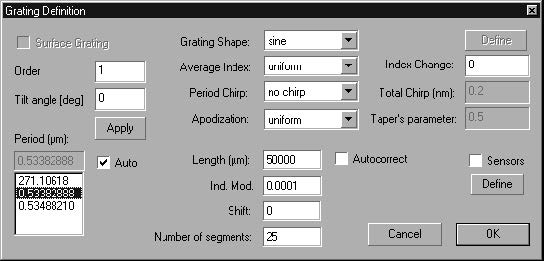
Define the Grating by the following parameters:
Surface Grating. Check this checkbox when you want to define a surface relief
waveguide grating.
Order. Define the order of the grating.
Tilt Angle. Define the tilt angle of the grating (in degrees).
Period. Define the grating period at the center of the grating.
Note: For a given set of modes the program suggests period values that match
the coupling conditions. If you enable the Auto check box, you won’t be able to
enter a period value other than the suggested one. To enter your own value of the
period, disable the Auto check box.
Apply. Press this button to re-calculate the default grating periods based on the
entered Order and Tilt angle values.
Grating Shape. The Grating Shape list box allows you to choose one of the following
options for the modulation of the grating shape: Sine, Rectangle, from file, or User
Defined.
Average Index. The Average Index list box allows you to choose one of the following
options: Uniform, Linear, From File, or User Defined.
Period Chirp. The Period Chirp list box, offers you the following options: Linear,
Quadratic, Square Root, Cubic Root, From File, and User Defined.
Note: Period chirp is defined as a variation of the grating period along the distance. The total chirp is defined as the difference between the first and the last grating period.
Apodization. The Apodization list box allows you to use one of the following options for varying modulation of the grating: Uniform, Gaussian, Hyperbolic Tangent, From File, and User Defined.
Length. In the Length box, you define the grating’s length. Enable the Autocorrect
check box to ensure that the grating has an integer number of full periods.
Ind. Mod. In the Index Modulation box, you define the amplitude of the index
modulation of the grating.
Height. In the Height box, you define the height of the surface relief grating. The
height modulation, measured in microns, is used for surface relief gratings in the
Single Waveguide and Waveguide Coupler modules.
Shift. In the Shift box, you enter the value that shifts the origin of the grating shape
function forward. The shift is measured in grating periods. For example, a value of
0.25 shifts the origin of the shape for a quarter of a period, i.e. the grating’s shape
becomes the cosine function.
Number Of Segments. In the Number Of Segments box, you enter the number of
subdivisions for the Transfer Matrix Method. For example, the non-uniform grating
can be divided in 10 uniform segments.
Sensor. Check this check box to define sensor parameters. You enable the Sensors
check box only when you are working with the Single fiber module.
Note: When you choose the From File option, the program invokes a spreadsheet
utility, and you can define the data table or read an external data file.
From File
The From File option exists in four of the list boxes in the Grating Definition dialog box
(in the Grating shape, the Average Index, the Period Chirp, and the Apodization list
boxes).
When you read From File data concerning average index, chirp or apodization (not
the grating shape), the program opens a table in which you can enter your data
manually or load an external file:
To use the From File option to enter data manually
| 1 | Parameters > Grating. |
| 2 | In the Grating Manager, select a grating object and click the Edit Item button. |
| 3 | In the Gratings Definition box, from the Average Index, the Period Chirp, or the Apodization list boxes, choose From File. |
| 4 | In the Table dialog box, enter the value of chirp or apodization for each grating segment. |
Note: You can add and remove rows by clicking the Add Row and Remove Last
Row buttons. You can also save your table or open an external file.
To use the From File option to load an external file
| 1 | Parameters > Grating. |
| 2 | In the Grating Manager, select a grating object and click the Edit Item button. |
| 3 | In the Gratings Definition box, from the Average Index, the Period Chirp, or the Apodization list boxes, choose From File. |
| 4 | In the Table dialog box, click the open button. |
| 5 | In the Open dialog box, define the file name and the type of file you want to open and click the Open button. |
To use the From File option to load the grating shape from an external file
| 1 | Parameters > Grating. |
| 2 | In the Grating Manager, select a grating object and click the Edit Item button. |
| 3 | In the Gratings Definition box, from the Grating Shape list boxes, choose From File. |
| 4 | Press the Define button at the right hand of Grating Shape list. |
| 5 | In the Open dialog box, define the file name and the type of file you want to open and click the Open button. |
The external data file Format
The external data file contains one or two columns of numbers in text format,
separated by a comma or a space.
Two Columns – If the file has two columns, the first column is the position along the grating length (for Average Index, period chirp, and Apodization) or the position along a single period (For Grating Shape). The second column is the defined Grating Shape, Average Index, Period Chirp, or Apodization value.
One Column – In this case, the column is the defined Grating Shape, Average Index,
Period Chirp, or Apodization value. It is assumed that the defined data are uniformly
distributed.
User Defined
The User Defined option is available in four of the list boxes – Grating Shape, Average
Index, Period Chirp, Apodization – in the Grating Definition dialog box. You can define
functions that determine the shape, chirp, and apodization of the grating. A special
environment provides you with the necessary tools to edit the function.
To choose the User Defined option
| 1 | Parameters > Grating. |
| 2 | In the Grating Manager, select a grating object and click the Edit Item button. |
| 3 | In the Gratings Definition dialog box, from the Grating Shape, the Average Index, the Period Chirp, or the Apodization list boxes, choose User Defined. |
| 4 | Click the Define button. |
| 5 | In the Used Defined Function dialog box, choose the desired options and click the OK button. |
Working With User Defined options
Since User Defined options are very important for your work, you may want to have a
look at the following example:
Let’s say that you want to use the User Defined option to define the Apodization
function. Follow step 1 and 2, described in the above procedure, and from the
Apodization list box, choose User Defined to open the User Defined Functions dialog
box. The User Defined Function dialog box is split into two: the editing area and the
display area.
The Editing Area
You define the function in the editing area. For your convenience, the editing area is
a simplified programming editor. To define a function, you type the function formula.
In the formula, you can use numbers, constants, variables, and other functions.
Standard mathematical operators are supported. The program keeps a list of
mathematical constants, design (global) variables, and mathematical functions.
In general, the User Defined function has one independent variable, called x, which
has the following ranges:
From 0 to Grating Period – in the user definition of Grating Shape.
From 0 to Length – in the user definition of Grating Chirp and Apodization.
The x-variable is called the global variable. Other global variables related to the
grating are the Grating Length and Period. You can use them in your function.
The Display Area
The graph of the function is shown in the display area.
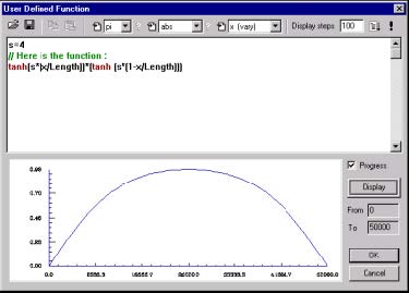
Working in the Editing Area
Since this example shows you how to use the User Defined option to define the
Apodization function, let’s assume that you need the Apodization function
tanh(s*(x/Length))*(tanh(s*(1-x/ Length))), where s = 4. All you have to do is type the
following two lines in the User Function Definition editing area:
s=4
tanh(s*(x/Length))*(tanh(s*(1-x/Length)))
Exploring the User Defined Function program editor
As mentioned above, the editing area is a simplified programming editor. You can not
only write your own functions but also test and debug the program. The format of the
language is very close to BASIC. For more information, see the Appendix A.
Using Combo boxes
![]()
There are three combo boxes. Each of them contains an icon and a list of options, as
shown in the example on the left.
The icon on the left side of any combo box is for inserting a selected item into the text
(at the cursor position). The list of options in the first combo box contains all constants,
in the second one all functions, and in the last one the actual global variables. Usually
x is a variable that varies in the x direction.
The question marks on the right side of the first and the second combo box will give
you a short help about a constant or a function. (Usually a value in constant and
syntax in function.)
Using the Display Steps box
![]()
You use the Display Steps box for testing. In this box, you type the number of points
you will calculate when you press the Display button in the display area. The number
you type in this box is not the number of points this function will calculate in a real
calculation. To do the calculation, just press the OK button in the display area.
Running the Program and Debugging
![]()
The User Defined Function program editor allows you to Debug and Run (Display) the
program.
Run, the “!” button, has exactly the same function as the Display button. It is put on
the Toolbar for convenience.
Debug. You can not only run your program but also debug it. If the function is not
simple, i.e. it may have an IF – THEN structure for example, and gives you bad results,
you can easily debug your program by pressing the Debug button and following the
prompts.
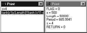
In that case, you will see two new windows. The first one contains the Source Code
and shows you where you are in debugging; the second one contains a list of all
global (system defined) and local (defined by you) variables.
Exploring the Display Area
In the display area, you see the actual graph. You can also define the variable range
of x in the From and To boxes.
The From and To boxes
Since in most cases, the variable values of x in those boxes are real, it is advisable
that you don’t change them. Only in Pulse calculation, when the Input Pulse is User
Defined and the Peak is set to 0, you may want to change the From and To range. To
change the range, just click the desired box (if it is disabled, it will be enabled) and
enter your parameters.
The Progress check box
![]()
If you enable the Progress check box, you will be able to see the Progress Bar while
the program is running. To perform this, you have to enable the Progress check box
and press the Display button.
You may want to disable the Progress check box if you are using some output
windows or FOR – NEXT loops that will give you many Progress/Message bars.
The Load and Save buttons
![]()
You can load or save any functions to disk as a separate text so that you can build
your own library of new functions.
Note: After you have explored all the options in the User Defined Function dialog
box, click the OK button to accept the definition and return to the Grating
Definition dialog box. For more information, see the Appendix A.