
File: New > Fiber Coupler
The Fiber Coupler Module
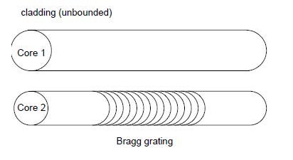
You use the Fiber Coupler module to model two fibers embedded in one infinite
cladding. The grating can be placed anywhere in the coupler. OptiGrating allows you
to adjust both the fiber coupler dimensions and refractive index profile and
photosensitivity profile.
You can optimize the coupling between the modes of the two fibers. There are two
mode options available: LP modes or full, vector modes (HE, EH, TE, or TM) of the
fibers. The vector modes option is only available for step-index fiber. The Fiber
Coupler module finds applications in co-directional and contra-directional grating
assisted coupler, direct and exchange fiber Bragg reflectors, and filters.
To select the Fiber Coupler module
| 1 | File > New. |
| 2 | In the New dialog box, click Fiber Coupler. |
The Fiber Coupler dialog box
In this dialog box, you enter the main data concerning the fiber coupler dimensions,
index profile, and photosensitive profile.
To open the Fiber Coupler dialog box
| 1 | File > New. |
| 2 | In the New dialog box, click Fiber Coupler. |
| 3 | In the Project window, click the Fiber/Waveguide Parameters button. |
The Fiber Coupler Profile dialog box options are described below.
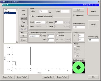
Fiber 1
Select Fiber 1 button to define the profile of fiber 1. The options for fiber 1 are same
as Single Fiber profile (see Single Fiber Profile dialog box).
Fiber 2
Select Fiber 2 button to define the profile of fiber 2. The options for fiber 2 are same
as Single Fiber profile (see Single Fiber Profile dialog box).
Distance
Distance is the width of the shortest common cladding of the coupler.
Note: To make sure the fiber coupler has common cladding, The outmost regions
of Fiber 1 and Fiber 2 should be defined by constant real index profile with Steps
equal to 1 with same index value.
Fiber Coupler Modes dialog box
After you have finished the data entry for the fibers in the Fiber Coupler Profile dialog
box, OptiGrating prepares lists of guided modes, which include separate calculations
for Fiber 1 and Fiber 2. The lists of guided modes are displayed in the Fiber Coupler
Modes dialog box. You can select one Fiber 1 mode and one Fiber 2 mode.
The options in the Fiber Coupler modes dialog box are similar to the one in the Single
Fiber Modes dialog box.
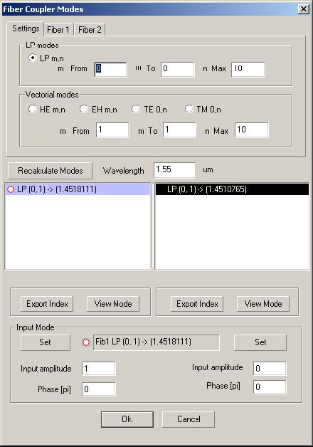
To compute guided modes in the Fiber Coupler Modes dialog box
| 1 | In the Fiber Coupler Modes dialog box, select one mode from the Fiber 1 Modes list box and one mode from the Fiber 2 Modes list box. |
| 2 | In the Fiber 1 Amplitude and in the Fiber 2 Amplitude boxes, type the desired values. |
| 3 | In the Phase boxes, enter the desired values and click the OK button. |
Clicking on either the Fiber 1 or Fiber 2 tabs will bring up the following choices:
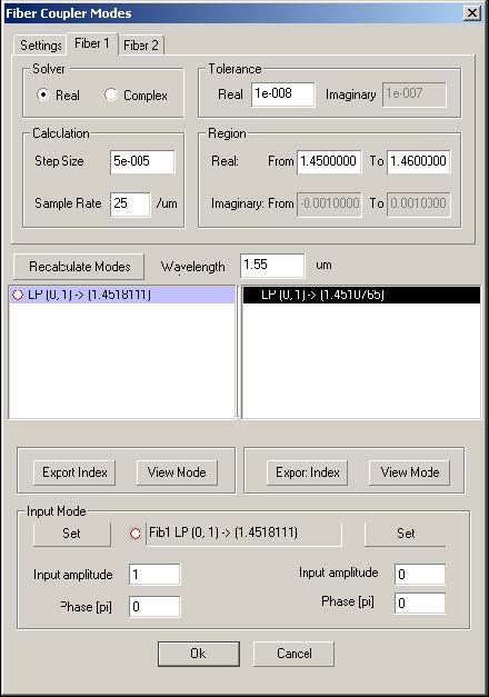
- Similar to the Advanced Settings option in Single Fiber Modes, choosing either
the Real or Complex button in the Solver box will determine which variables you
may change.
In the Real option, real solutions will be sought in the interval specified in the Real
From and To fields. The solver will step through this interval in steps of Step Size.
In the Complex option, solutions are sought in a rectangular region of the complex
plane as defined by the From and To fields in both real and imaginary. The Complex
option uses an advanced technique for finding the roots as described in the Technical
Background chapter of the OptiGrating manual.