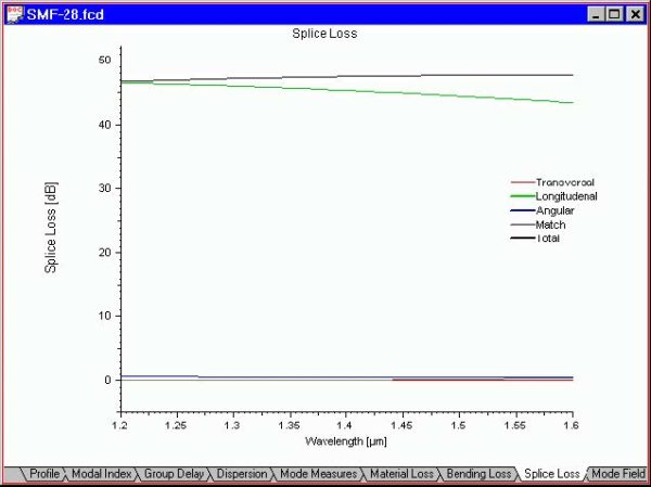
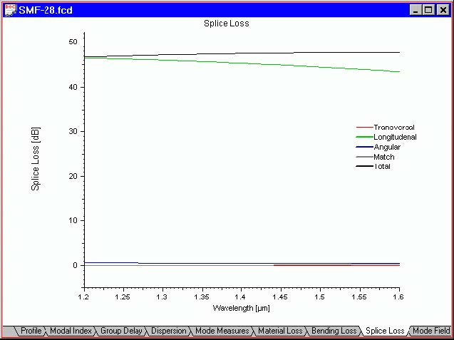
The “Splice Loss” view shows you the transversal, longitudinal, and angular
misalignment loss, as well as the mode match and total splice loss vs. the scan
parameter. The default scan parameter is the wavelength. You can change the scan
parameter in the “Properties of Fundamental Mode” dialog box.
To access this view do one of the following steps:
| Step | Action |
| 1 | Select the “Splice Loss” tab in the “Views” window |
| 2 | Select “Views/Splice Loss” on the “View” menu |
 Mode Field view
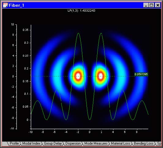
The “Mode Field” view shows you a topographic plot of the mode field. The displayed
mode is the one selected in the Modes dialog box. You can change the display mesh
in the Global Settings dialog box. Also a X- or Y-cuts (or both) of the mode are shown.
To access this view do one of the following steps:
| Step | Action |
| 1 | Select the “Mode Field” tab in the “Views” window |
| 2 | Select “Views/Mode Field” on the “View” menu |
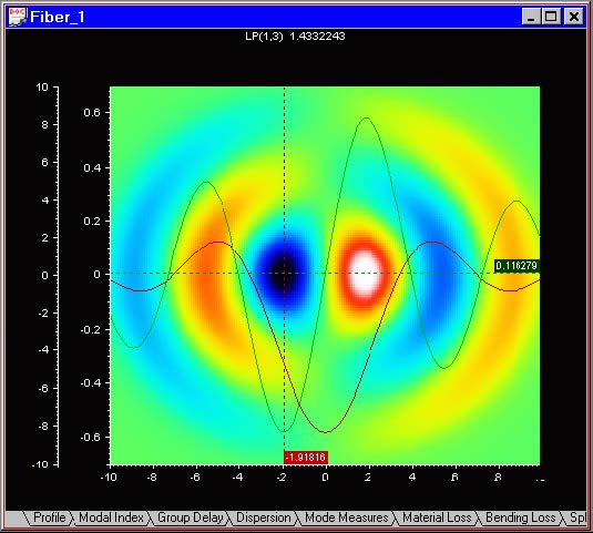
 If the option “Amplitude”, instead of “Intensity” has been selected from the right-button
context menu “Graph Properties”, then the ”Mode Field” displays a topological color coded pattern and 2D X- and Y-cut cross sections of the amplitude of the same field, as shown below: