
Base
| Full Name | Lizzie Li |
| Organization | HNU |
| Job Title | Ph.D |
| Country |
Forum Replies Created
Hi, vignes
I am working with long period fiber grating. My work at present focuses on the study of LPFGs theory.
Yes, it works. Thanks Steve and vignes very much. It seems the document of OptiFiber has something wrong about the description of scanning parameters.
Best Regards.
Thanks vignes,
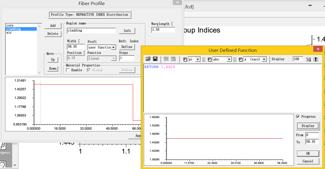
it seems we cannot scan modes in profile design layout as shown in fig. 1. Please check.
Attachments:
Hi, Steve
I have reproduced Fig. 10 by using matlab based on the numerical method reported by E. Anemogiannis, et al. The fiber parameters are: core radius 2.5μm, cladding radius 62.5μm, core refractive index 1.4573, cladding refractive index 1.45, index modulation amplitude 3.6e-4, grating length 25mm and grating period 570μm. However, the transmission spectrum obtained by using the formulas provided by T. Erdogan presents a large wavelength shift if compared with Fig. 10 (see the figure attached below). Using OpitGrating still cannot get any resonances.
After checking the document of OptiGrating, I think the definition of the grating index profile (see page 26) is very different from that of the paper reported by T. Erdogan, which may be the reason why OptiGrating cannot get the same transmission spectrum as Fig. 10. However, I don’t know how to define the same index profile in OptiGrating as that of Fig.10.
Thanks.
Appendix
grating index profile defined in OptiGrating (page 26): n(x,y,z)=n0(x,y)+Δn0(x,y,z)+Δn⋅P(x,y)⋅A(z)⋅f[Λ(z)⁄cosθ,z]
References
E. Anemogiannis, E. N. Glytsis, and T. K. Gaylord. Journal of Lightwave Technology, Vol. 21, Issue 1, 218-227 (2003)
Attachments:
Thanks Steve,
According to the paper reported on the LPFGs, the default value of parameter “m” is 1 in the literature. In addition, I do not know where the parameter “m” can be defined in the OptiGrating.
Hi, Marek
I want to obtain the Fig. 10(b) in the reference paper using OptiFiber. But the simulated transmission spectrum shows a big difference with Fig. 10(b).
Thanks.
Thanks Steven,
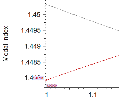
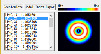
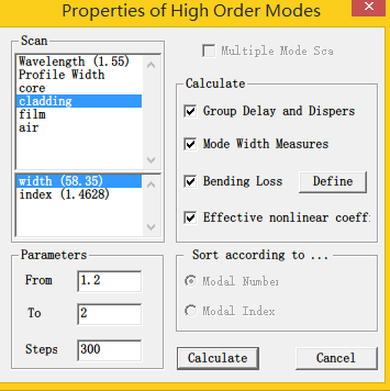
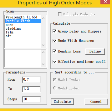
I select “cladding” in the upper pane and “width” in the lower pane, and then set the range of the scanning width from 1 to 1.5 (means 1L to 1.5L). The scanning width equal to 1 means the original width of cladding is not shrunk or expanded. So, the effective refractive index of the cladding modes will not change. However, the calculated effective index of LP02 mode with scanning width equal to 1 is 1.44793 (see Fig. 1) which is smaller than that (1.4627469) without setting the scanning parameters (see Fig. 2).
Thanks vignes,
The “Scan” section is split into two panes. If I select the region of the cladding in the upper pane, the parameters I can change in the lower pane are only the wavelength range and the steps, as shown in Fig. 1. This means that the cladding width is a constant. In addition, if the profile width is selected the profile width can be scanned within the specific limits as shown in Fig. 2. However, I note from the OptiFiber documents that this profile width, I think, is the total width of the whole fiber profile, as it said that the profile as a whole within user-specified limits, for example between 0.8 and 1.2 of the original width. This means that all spatial dimensions of the original design are proportionally shrunk/expanded at regular steps from 0.8L to 1.2L, where L is the initial width.
So is there still no way to calculate the mode index depending on the cladding width? The .fcd file is attached here.
It is the effective index of mode of the fiber.
What’s kind of grating do you want to simulate?
Yes, mode index is different from the effective refractive index. After defining the fiber, you can get the effective refractive index by calculating modes.
OptiFiber can calculate the effective refractive index of fiber taper. And you can define the taper you want to simulate.
Thanks Steve Dods very much.
Thanks Steve Dods,
As you said, I have to look at the mode field pattern if I want to know whether a single mode is cladding mode or not. So if I want to calculate the refractive index of cladding modes of multimode optical fiber with hundreds of core modes, I should check out every single core mode to find the cladding modes, especially those modes which are close to cladding mode. Apparently this is not convenient.
I am thinking why OptiFiber does not add a new function which is capable of calculating and simulating the core modes and the cladding modes, respectively.
Thanks for your attention.
But how can I do this calculation? Is there any example about this kind of simulation? I do not know how to set the parameters to calculate the modal index of cladding modes even though I have calculated the core modes index.