
Base
| Full Name | alistu |
| Organization | SE |
| Job Title | Student |
| Country |
Forum Replies Created
Dear Ahmad,
Thank you very much for your response. I believe the number of FFT points are represented as “maximum number of subcarriers” in the BER Test Set.
I do have basic familiarity with OFDM theory, but the BER Test Set calculation method is still not clear to me. To be more specific, if I want to implement an OFDM-CDMA structure, where every bit of the binary input is first multiplied by a code word, it is easy to implement the multiplication block through Matlab Component after the BER Test Set – please refer to an OFDM sample. That way, since the sequence length in the layout parameters is fixed, the overall bit rate and the input word length are reduced. However, I cannot figure out how to define the BER Test Set bit sequence the same as the Matlab Component output, so it correctly calculates the error.
Another approach is to replace the BER Test Set with a suitable program via Matlab Component, but it would then require a solid knowledge of how the BER Test Set works in OptiSystem. And that is why I started the thread.
Thank you again for helping me out.
Best regards,
Alistu
Hi Ahmad,
Thank you for your response. Regarding BER for OFDM, the help section only emphasizes in a few lines the importance of assigning the same values to the component as the ones used in OFDM transceivers with no other explanations on how the parameters are considered in calculations.
Great! Thank you very much Ahmad.
.
The file:
Hi,
Here I have attached an .osd file of an implementation of a bidirectional system which makes use of coherent QAM both in downstream and upstream. When the downstream signal passes through the channel, it is splitted to two branches, with one going to the downstream receiver and the other to upstream transmitter, to be used as an optical source instead of the laser (which is the whole point of using remodulation technique, BTW). The problem is, though, that there is no upstream signal after the bidirectional fiber, as it can be seen by ‘Optical Spectrum Analyzer_2’. What is the problem?
The system error is not important for me here. I just want to have the signal. Thank you in advance!
In the most common cases, remodulation makes use of RSOA or power splitters. It is not important to me whether or not the system works well in terms of error – that can be fixed. I’d rather to get it to work first, to send the upstream signal through a birdirectional channel and get a signal at upstream receiver.
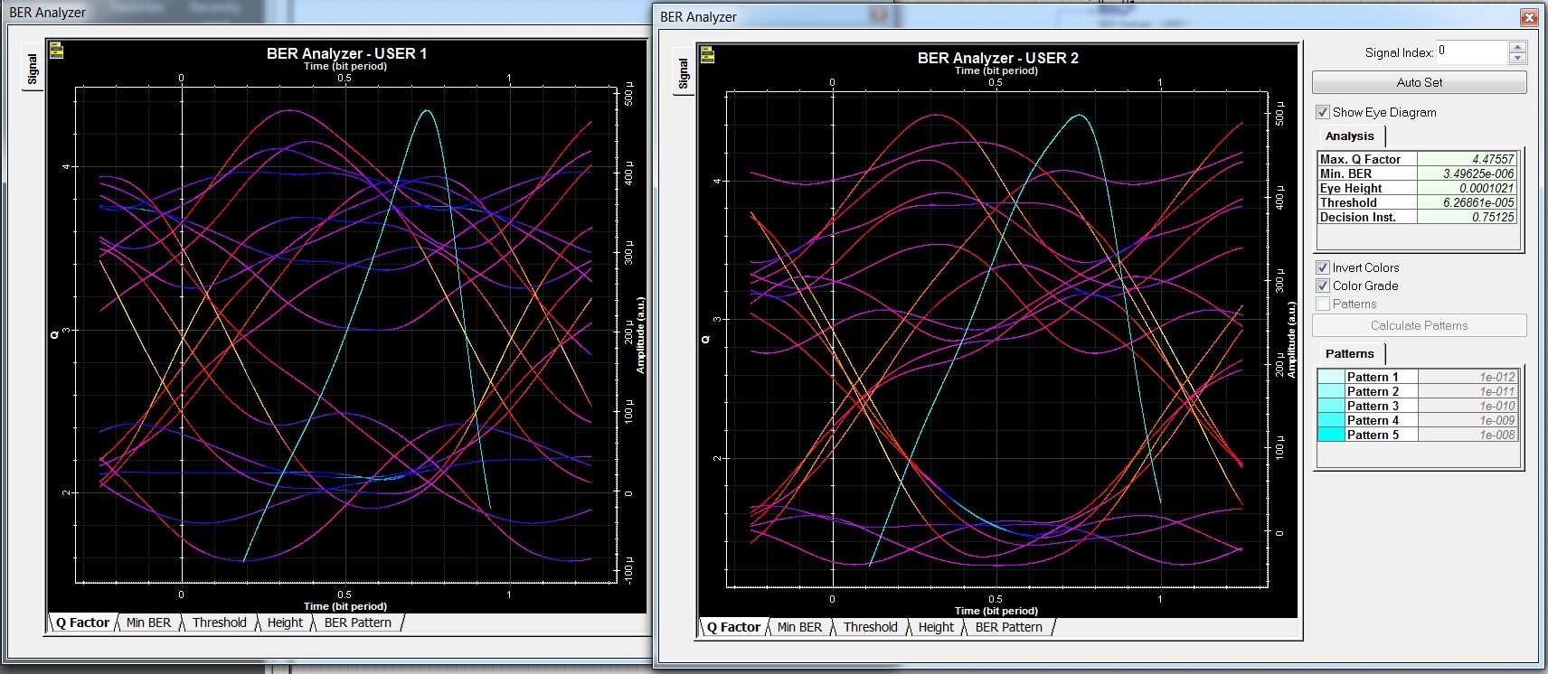
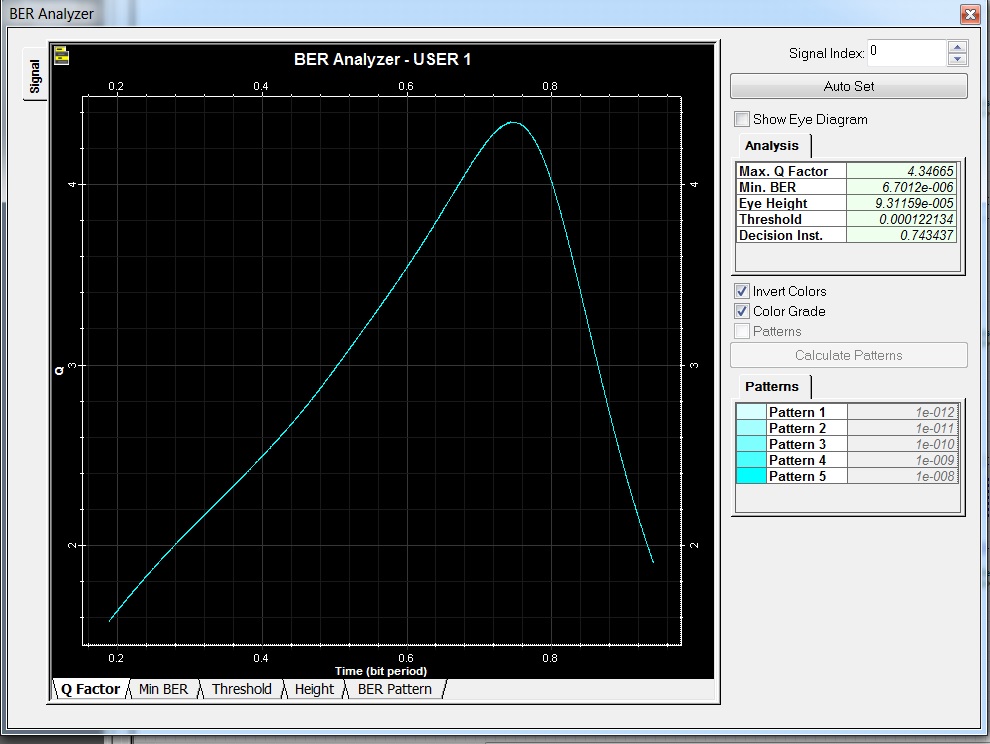
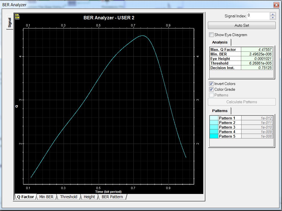
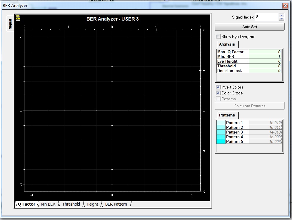
Yes, here’s the screen shot from all users.
BTW, did you try to change the FBG frequencies to make it work?
Hi Irfan,
This file is OptiSystem SAC-OCDM sample as far as I am concerned (so you can find it in OptiSystem samples). I ran the simulation and it went smoothly with acceptable results except for the third user (which you should first enable in the simulation BTW). If you cannot open the file or do the calculation, this is a technical issue and you should contact Optiwave, which will probably answer after the weekend.
I suspect something might be wrong with the way the third code is generated by FBGs. I haven’t worked much on SAC-OCDMA, but if you are interested to know how the codes should be generated, I suggest you thoroughly go through the related comprehensive discussion in the link below:
Regards
Hi,
If my perception of the issue is right, you may be able to troubleshoot by doing as I have stated in the previous comments above. Otherwise, please contact Optiwave via the mail address provided by Damian on this page.
Regards
Thank you Mohamed and Gokul. It was indeed useful.
Hi Ranjeet,
I remember Damian mentioning about using BER test set instead of BER analyzer on several occasions, once explaining the reason to be traning symbols, so I am not sure if BER analyzer can be used in the case you have mentioned. I’d use both to find out, though.
In order to use pilot symbols, you need to use OptiSystem 13 OFDM components. OS12 OFDM components do not have such capability. You can refer to the available OFDM examples in OptiSystem 13 samples where pilot and training signaling is used.
Regards
You’re welcome Gokul. You are right. As I mentioned previously, the BER analyzer does not take the training symbols and such factors into account and consequently, the results calculated by it cannot be very accurate. Otherwise, this has nothing to do with PRBS generator component itself. So I believe it would be more accurate to say that BER analyzer should not be used in such systems and BER test set should be used instead.
Regards