
- This topic has 23 replies, 3 voices, and was last updated 9 years ago by
 Ibn Aziz.
-
AuthorPosts
-
-
March 12, 2015 at 7:36 am #18565
 Ibn AzizParticipant
Hi every one !
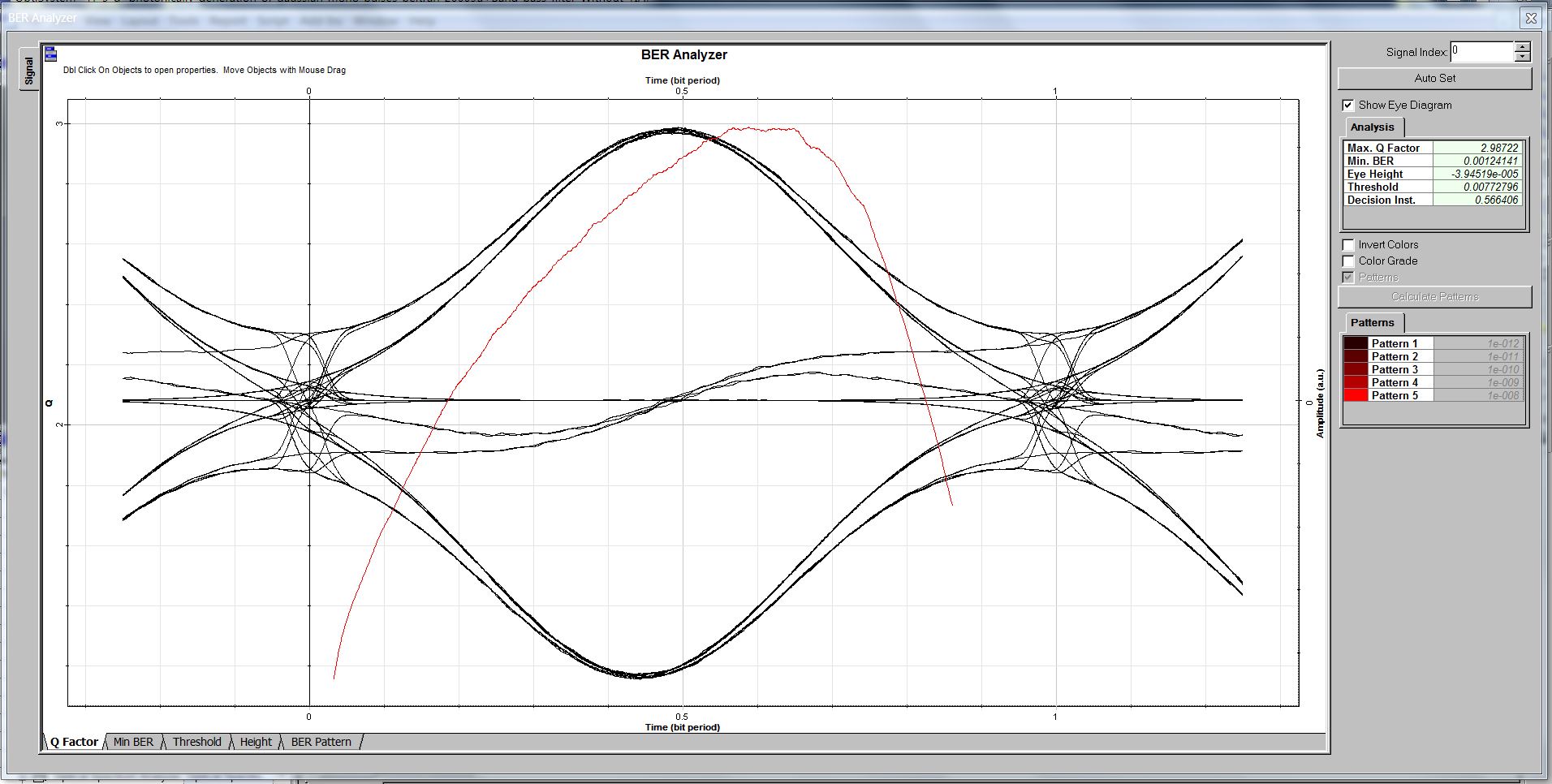
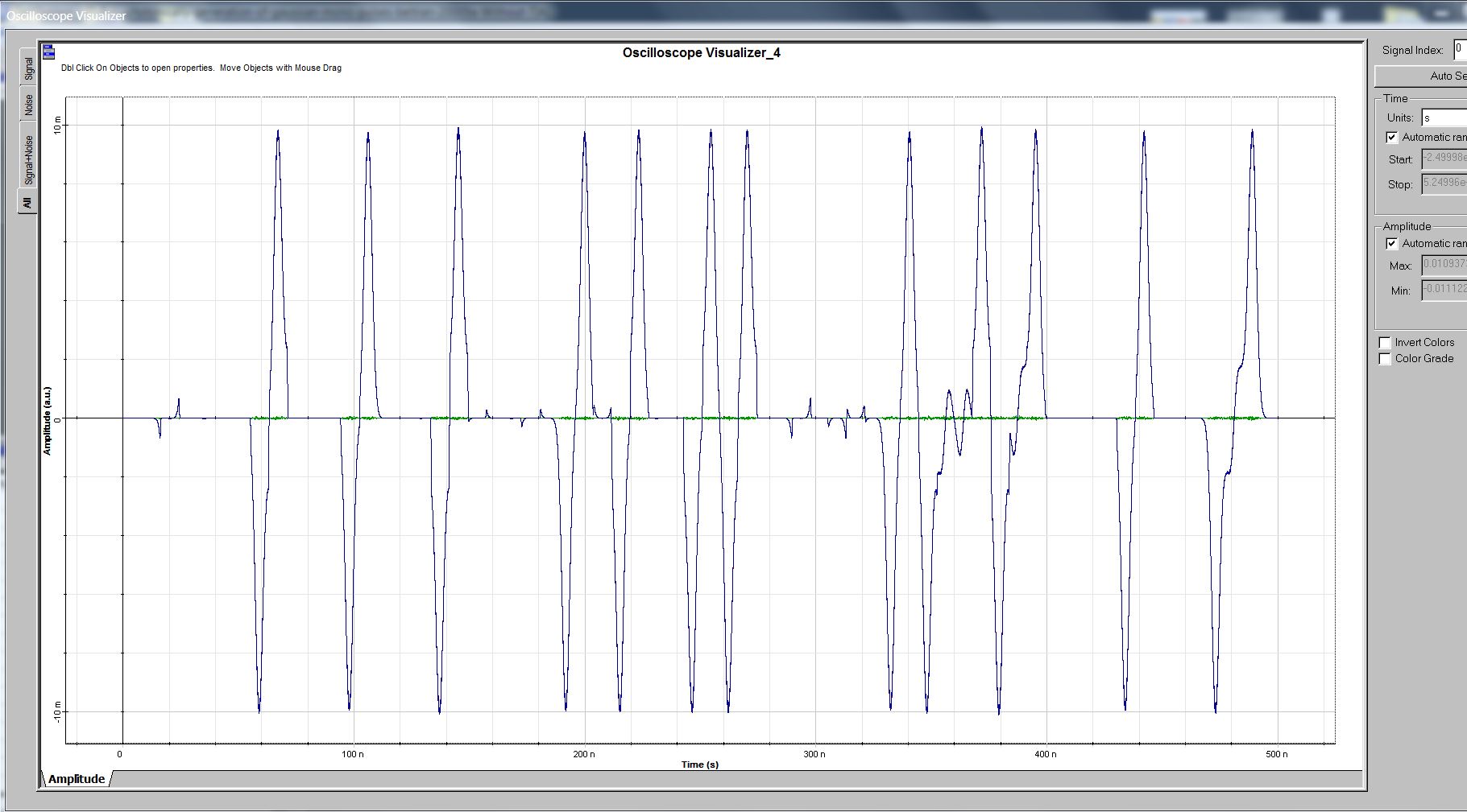
Hope u r fine.I am using Gaussian Mono cycle pulse in my research work. But when i want to analyze and measure BER of Gaussian Mono Cycle pulse (fig attached below) by using BER Analyzer then i got “Two Eye diagrams” as shown in fig below.
I am getting these two Eye Diagrams because BER analyzer in Opti sys took negative and positive going cycles of Gaussian Monocycle a separate signals. Therefore BER analyzer made two eye diagrams one for each cycle.
But this is wrong, because BER analyzer should analyze and measure BER for Gaussian mono cycle as a one complete signal rather than take two components of Gaussian mono cycle signal separately. Further, it must display findings and result in only one eye diagram.
Therefore, Can some body tell me how to make BER Analyzer able to take Gaussian mono cycle one complete signal and display result in one Eye Diagram.
I will be very thankful to you for your kind response.
P.S i am transmitting NRZ data from transmitting side.
Best Regards -
March 12, 2015 at 11:09 am #18580
Damian Marek
ParticipantIt might not be possible to calculate the BER from the eye diagram alone. Could you please attach your project file?
Thanks
-
March 12, 2015 at 11:21 am #18581Ibn AzizParticipant
Damian thanks alot for responding, file is attached below.
Damian I need to find both Eye diagram and BER but first problem is that i am getting 2 eye diagrams which should be only one (further detail is discussed above).Hw can i come out of this ?
2. Kindly guide me how will i measure BER for such scenario or when i am using Gaussian Mono cycle pulse signal ??
P.s I am using Opti sys 7
Best Regards
Stay BlessAttachments:
-
March 12, 2015 at 1:27 pm #18584Participant
Hello,
What type of eye diagram are you expecting for the Gaussian Mono Cycle? Fundamentally, the modulation schemes are different between a NRZ pulse and the monocycle gaussian format. From the eye diagram it looks exactly as I would expect it to considering the modulation type and the input electrical signal.
Our BER Analyzer assumes an NRZ or RZ modulation format and calculates the BER from the eye diagram based on that, which of course does not apply to this application. In your case the best bet is to use the BER Visualizer for a quick visualization of the signal, but I think for a rigorous BER calculation you will need to use the BER Test Set. There are plenty of topics on the forum on the use of the BER Test Set if you are unfamiliar with it.
Regards
-
March 12, 2015 at 1:51 pm #18587Ibn AzizParticipant
Thanks Damian for your kind elaboration !
I am expecting a general eye diagram which works for all NRZ scheme (which don’t have any negative portion or down word slop as shown in above attachment) but as u stated above, it will not apply here.
Actually from the transmitting side i am sending NRZ data but in return at receiver side i am getting Gaussian mono cycle. So when i plot Eye diagram i should get eye diagram like all NRZ data but i didn’t get that shape because BER analyzer understand only RZ or NRZ type data.
ok Damian I will use BER visualizer and BER Test Set to find the require Eye diagram and BER. I hope it will work.
I am very thankful to you Damian, u always there to help any community member.
Best Regards
-
March 12, 2015 at 2:10 pm #18589Participant
You are most welcome! The alternative is to perform some type of analog demodulation to revert back to an NRZ format.
-
-
March 12, 2015 at 2:37 pm #18590Ibn AzizParticipant
Yes Damian, i will have to bring it back to NRZ format. Actually Damian i tried absolute component in my work to clip off negative cycle which brings signal to its original form and helps to measure BER. But in this way the only anomaly i will have, is in amplitude of the signal.
And Damian if u know any type of analog demodulation (for example ??) that helps to regenerate NRZ fromat signal also share.
Best Regards
-
March 13, 2015 at 3:01 am #18611Ibn AzizParticipant
Dear Damian as i am using Opti sys 7, so according to my knowledge there is no such component like BER Test Set is available in it but if any such component in opti sys 7 who has some functionality resembling BER Test Set plz share.
I will be very thankful to you.
Best Regards
-
March 13, 2015 at 10:00 am #18636Participant
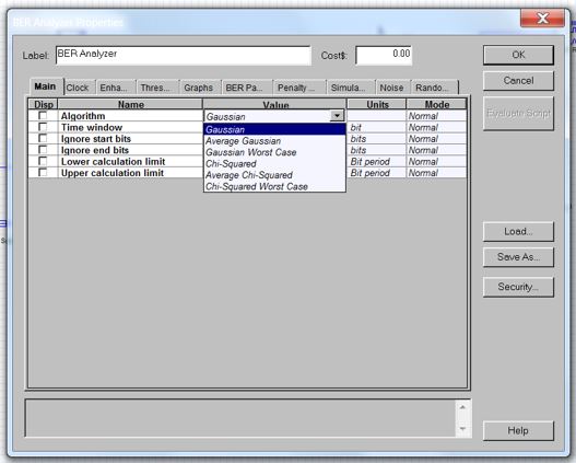
You should be able to change the Algorithm for the BER Analyzer from Gaussian to Measured mode.
-
-
March 14, 2015 at 1:21 pm #18671Ibn AzizParticipant
Damian Thanks alot for your reply.
Damian i read your similar suggestion in many other forum topics in which u suggested the similar approach but u didn’t share how can we change BER anlyzer algorithm from Gaussian to measured mode ??
i have gone through the many tutorials and help doc but couldn’t find any way…
Kindly any one who knows the procedure or method to change BER analyzer algorithm from Gaussian to Measured mode for Opti sys 7 plzz share.
I will be very thankful to you for your kind suggestions.
Best Regards
-
March 23, 2015 at 1:28 pm #18936Participant
Right-click the component choose Component Properties. Change the Algorithm from Gaussian to Measured.
Cheers!
-
-
March 24, 2015 at 9:10 am #18954Ibn AzizParticipant
Thanks Alot Damian for your kind response !
But there is no such option like “Measured” over there. I am sharing in below pic all options which i get after scrolling down. kindly tell me how can i use measured value in BER analyzer.
Regards
Attachments:
-
March 24, 2015 at 5:24 pm #18978Participant
Oh sorry about that. I forgot you are using OptiSystem 7. I am not sure what components were available in that version you might try the BER Test Set if it there.
-
April 5, 2015 at 6:30 pm #19298
 Jaffar Emad KadumParticipant
Dear Aziz,
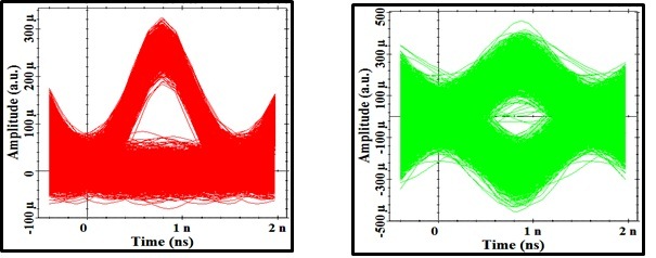
The two eye diagrams because you are working in ( BI-PHASE ) modulation format. The analyzer takes the complete cycle not only the positive or negative part of signal. BUT, these two diagrams one for ( 1 and 0) which are represented by a monocycle and its reflection
IF you work in ON-OFF keying modulation format you will get one eye diagram. as attached pic
Attachments:
-
April 5, 2015 at 7:19 pm #19302Jaffar Emad KadumParticipant
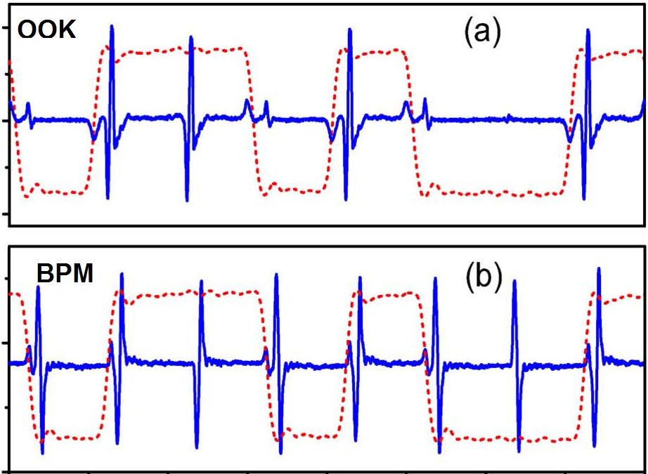
Find also these waveforms of BPM and OOK modulation formats. You can notice the change in the phase of monocycle signal in BPM according to the input binary data.
Attachments:
-
April 7, 2015 at 1:12 am #19336Ibn AzizParticipant
Thanks a lot Dear Jaffar for your kind response,
1. I am working in Uni-phase modulation format and u can verify it from the signal graph attached above (I am also attaching it below).
That’s the problem I don’t know why i am still getting two eye diagram ?2. I’m using NRZ pulse generator and always work in On Off keying format (I am attaching project file where u can verify it)
Further, just for verification, Can u tell me how can I set On off keying in Opti sys 7 because there is no option about OOK modulation format in my setup.
3. As I could not get any solution to this problem so I decided to transmit only “Gaussian pulses” in UWB over fiber transmission instead of “Gaussian mono cycle pulse”, Is this right or wrong decision ?
4. I am searching different references where they have used Gaussian pulses in UWB over fiber transmission but could not find any good reference from reputable confreres/ journals like JLT, OFC etc.
Have u notice any work/research paper/ journal which had used Gaussian pulses in UWBoF transmission ?? kindly share it.
i am thankful to you for ur participation at post.
Best Regards -
April 7, 2015 at 1:19 pm #19355Jaffar Emad KadumParticipant
Dear Aziz
Unfortunately now I do not have optisystem to check your system. I am sure there is a small error somewhere. you can attach the photo of optisystem design so I can comment on it. I have four papers about UWB signal generation from monocycle to fifth-order derivative Gaussain pulses operated with OOK and BPM modulation formats and all implemented in Optisystem.
It is incorrect to transmit Gaussian pulses for UWB communication. The UWB signal must be Gaussian monocycle or higher order derivative of Gaussian pulse for example Doublet or Triplet so that the power spectrum density will be comply with FCC mask..
This link is my latest paper published in British journal regarding the optical generation of Gaussian monocycle and doublet pulses with OOK and BPM modulation. -
April 8, 2015 at 1:24 pm #19417Ibn AzizParticipant
Thanks a lot Jaffar for your kind participation,
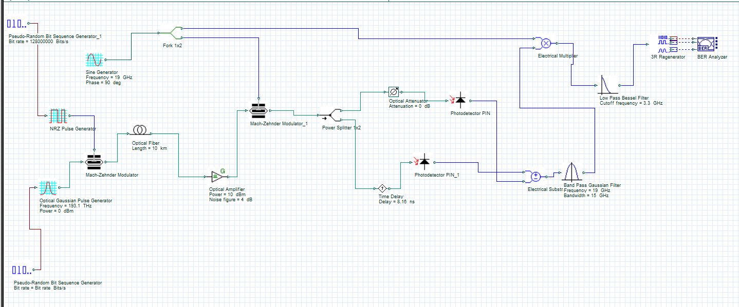
I am attaching picture of my setup and also the paper which I am simulating (the setup diagram is at page 4 of research paper), u can check them in below attachment.
Kindly comment where I am getting wrong so that I beocome able to find BER and eye diagram, because still I have not found any solution to this problem.
I have saved your paper but did not studied due to difference in working domain but now I will study them, to get an idea of how u have done calculation of BER and eye diagram in Opti sys for mono and duplet pulses.
I don’t know why your upper shared link is not working, kindly email me your paper at engr.bilalaziz@gmail.com.
Best Regards
-
April 8, 2015 at 2:22 pm #19422Jaffar Emad KadumParticipant
Dear Mr.Aziz
Here is my paper and I received your system. I will check it and respond as soon as possible.
Attachments:
-
April 9, 2015 at 12:58 am #19444Ibn AzizParticipant
ok thanks alot Jaffar,
i will wait for ur response.
Best Regards
-
April 10, 2015 at 3:12 pm #19578Jaffar Emad KadumParticipant
Dear Aziz,
I see you are using different method from the paper, you used optical Gaussian pulse generator, but in the paper not !!
-
April 12, 2015 at 4:25 pm #19614Ibn AzizParticipant
Dear Jaffer,
in paper author worked in real world but i am working on simulator that’s why i used Gaussian source instead of mode lock laser.
Jaffer as i have gotten Gaussian mono cycle pulses after photo detection which u can verify from graph attached above but the problem i am facing in my opinion is in BER analyzer because my BER is unable to give me results i.e. single Eye diagram.
So, I don’t know what setting should i apply in BER analyzer to get single Eye diagram ?
In your paper jaffer have u changed any setting at BER analyzer ?? or just connected BER analyzer with other components to find BER and eye diagram using default settings ?
Regards
-
April 12, 2015 at 4:43 pm #19616Jaffar Emad KadumParticipant
Dear Aziz,
Note that the author was used this configuration to obtain Gaussian pulse so the setting used may be specific for this reason. I think the components used in the paper are available in optisystem.
Usually I don not change any parameter. But I use careful consideration of filters frequencies and layout parameters of optisystem they are very important .
I think The problem in your design is the frequency of lowpass filter. It should be (0.75*Bit rate) also try to check to frequency of bandpass filter to fit your requirement
-
April 21, 2015 at 10:39 am #20000Ibn AzizParticipant
Thanks Jaffer for ur participation !
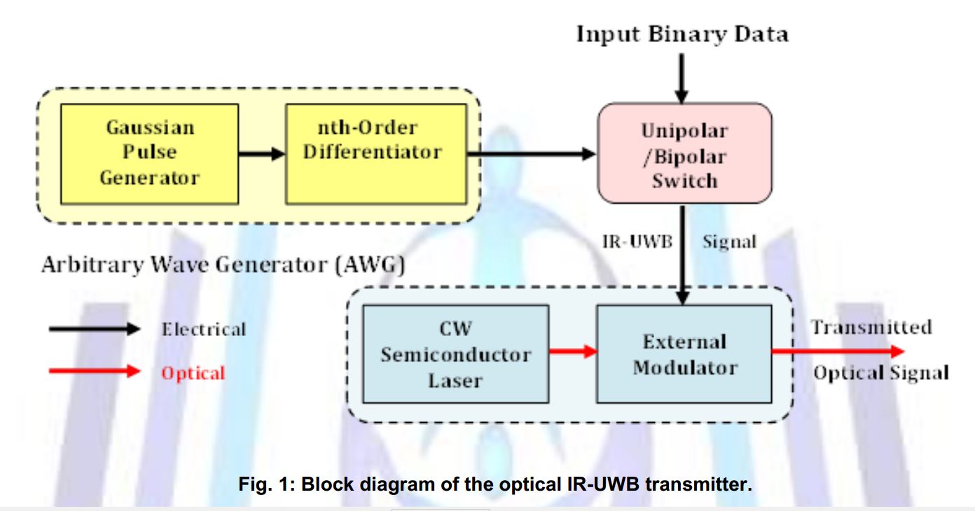
Jaffer i couldn’t resolve above issue (might be due to having Opti sys V-7) and now I started working on your paper name “Transmission Performance Investigation of IR-UWB Signals over Existing optical fiber Transmission link “.
1. I want to know what component u have used as “High speed Uni-polar switch (Electrical)” for modulation of Binary Data ?? as there is no such component available in Opti Sys V-7 libarary. I am attaching fig from ur paper as follow.
2. What type of digital data format u have used in ur paper ? NRZ or RZ ?
I will be thankfull to u.
Best Regards
Attachments:
-
-
AuthorPosts

- You must be logged in to reply to this topic.