
- This topic has 27 replies, 4 voices, and was last updated 8 years, 7 months ago by
 gaganpreet Kaur.
-
AuthorPosts
-
-
September 6, 2015 at 5:51 pm #24392
 MHD NAParticipant
Hi optiwave members;
I have designed RoF diagram but when i made calculation, it takes long time about 2 hours for fiber_1 calculations…..what’s the wrong in my attached diagram.
N.B. i am working on optisystem 7.regards;
Attachments:
-
September 7, 2015 at 2:10 am #24402
 alistuParticipant
Hi Mohammad,
The reason for calculations taking so long is that a lot of power is injected into your lines and therefore, nonlinearities occur. I suggest that you lower your amplifier gains to 10 dB (which is enough for the attenuation caused by each optical fiber) and then start simulation.
Regards
-
September 7, 2015 at 5:39 am #24406
 Ashu vermaParticipant
High power cause calculation time due to non linearities I have analzed you system ,your calculation time will reduce if you calculate edfa gain as 50 km smf x 0.2 dB attenuation per km which is equal to 10dB.but your systen has some problem that i couldnt get signal on visulizer.corrupted signal is there.please share paper you wqnt implement for more detailes
-
September 7, 2015 at 7:52 am #24407MHD NAParticipant
Thank you Alistu and Sam Sung; and here you are Sam Sung the wanted paper that I want to implement.
I need your help as soon as possible. -
September 7, 2015 at 11:53 am #24410Ashu vermaParticipant
Welcome Namera,it would be great if you again attach the paper,i think you forgot to attach paper or system may missed the file you uploaded.We will help you as immediate we can and try to reproduce your paper.Thank you
-
September 7, 2015 at 4:23 pm #24416MHD NAParticipant
Sorry my friends for missed paper. Here you are.
Attachments:
-
September 8, 2015 at 2:35 am #24419alistuParticipant
Here is your modified simulation file. The only problem it had was that you had forgotten to set channels frequencies (on channels tab) for the demultiplexer the same as the transmitted wavelengths. I also inserted two other BER analyzers the way depicted in the paper and the system seems to work fine according to the paper.
Regards
Attachments:
-
September 8, 2015 at 4:53 am #24421MHD NAParticipant
Thank you alistu for your effort, unforunaltly the attached osd doesn’t open by my optisystem 7. Could you save it in another way to open by optisystem or take a screen shot for the modified parameters, please?
Regards;
-
September 8, 2015 at 5:09 am #24422alistuParticipant
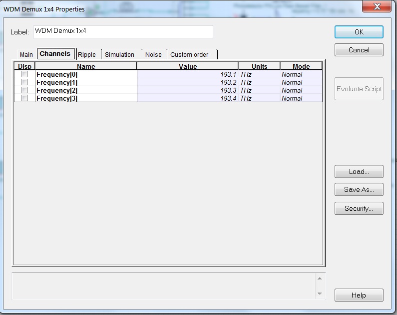
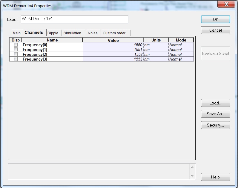
You’re welcome. Please open your own osd file (for which you have modified the amplifier powers and changed them to 10dB) and double-click on the WDM Demux 1X4. Then click on the “channels” tab and you’ll see the window depicted in screenshot named “sc1” attached. Now change the parameters as it is shown in the screenshot named “sc2” attached to my comment, and that’s it.
Cheers!
-
-
September 8, 2015 at 5:49 am #24425MHD NAParticipant
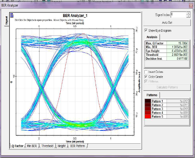
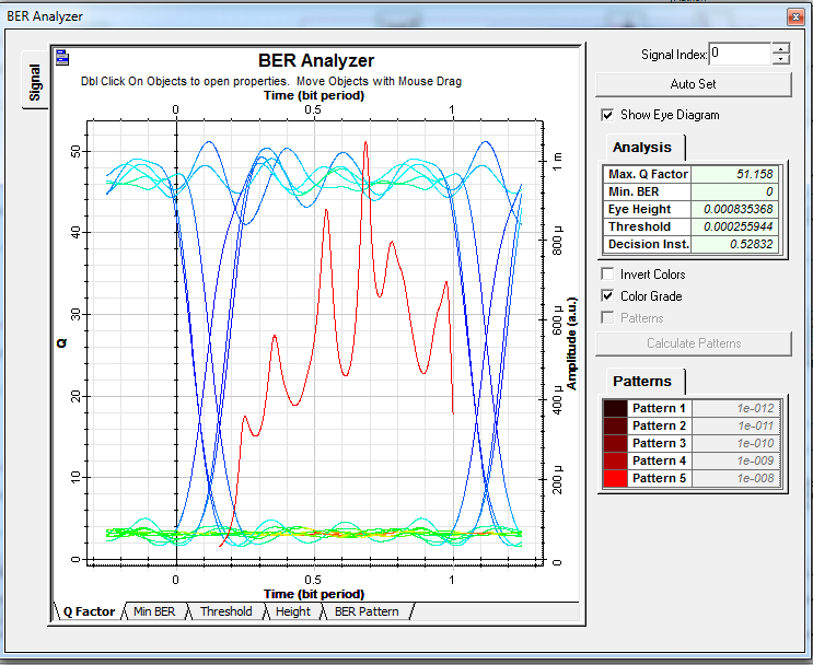
Hi alistu, I have done as you advise me but my results doesn’t look like the results in the paper.
for example; look at the BER results after modification and itself in paper, there is a big differentiation between them.
What can I do to be as the results in paper?Attachments:
-
September 8, 2015 at 6:27 am #24428alistuParticipant
It’s sometimes very difficult to get to the results the same as the ones in a paper. However, I think your results are acceptable and you have a greater Q-factor and better bit error rate than the ones obtained in the paper. I suggest that you go through the paper again and see if there are parameters you have set differently in your implementation. And by the way, the paper’s results have been obtained using Optisystem 9, while yours have been obtained using Optisystem 7. I cannot say that doesn’t affect the results for sure.
-
September 8, 2015 at 1:04 pm #24468MHD NAParticipant
Thanks alistu; is it reasonable value of BER in my project?…..I have doubt about this value.
Regards;
-
September 8, 2015 at 2:00 pm #24481alistuParticipant
You’re welcome Mohammad. Your simulation results give great amounts for Q-factor, and the bit-error-rate acquired by the system in the paper you are working on has a non-zero value, while yours is zero, which is the least amount you can get! So I’d say yes, your BER is quite acceptable. Please compare the eye openings in both images you have attached with regard to the amplitude unit.
Regards
-
-
September 8, 2015 at 1:21 pm #24474Ashu vermaParticipant
What value you are reffering too? In general according to ITU,system q factor should be 10^1 and powers of it and ber should be in the range of 10^-9 to 10^-12.10^-9 is maximum error error rate that can be accepted.
-
September 8, 2015 at 4:14 pm #24484MHD NAParticipant
Hi alistu;
I think you said the amplitude of transmitted signals affect on eye diagram, so if i modify the power of signals,the eye diagram changes?
what are the other factors affect on eye diagram? -
September 8, 2015 at 4:28 pm #24485alistuParticipant
I think I explained it a little unclear. What I meant was that if you take a look at both eye diagrams, you’ll notice the one belonging to the paper is about 20 a.u. open, while yours is about 50 a.u. open. So your system implementation has acquired a better Q-factor than the one acquired for the simulations in the paper.
-
September 9, 2015 at 4:10 pm #24511
 gaganpreet KaurParticipant
i would like to know if its ok that my DWDM design is taking 20 hrs of simulation through HNLF in optisystem 7.0. also i amunable to open any attached .osd files posted on this forum
-
September 9, 2015 at 4:30 pm #24512alistuParticipant
That is definitely too long! But please attach you osd file so that it would be possible to analyze it. I suggest that you take the power factor into consideration and lower the power to see if the simulation time is reduced. The osd file I have attached has been saved in version 13.0.3 and if your version is older, you can’t open it.
-
September 10, 2015 at 1:20 pm #24563Ashu vermaParticipant
Hello Gagan ,the time you mentioned above is too long.As far as Dwdm system is concerned then the total transmitted power is high than a single channel.The major reason for the long calculation time is your power Secondly you are using HNLF which is realized by increasing non linear index gamma .Now small power even can take more time in hnlf due to very small affective area of fiber and due to gamma .Moreover if you used Smf and dcf in your system then it will take very much time.The cause you need address is your power and could you please tell how many channels you fed to HNLF? Attach system file for better help And there is some reduction in calculation time if you use latest version.
-
-
September 10, 2015 at 3:09 pm #24566gaganpreet KaurParticipant
————— Message deleted by moderator due to policy violation —————
-
September 10, 2015 at 3:15 pm #24568alistuParticipant
Hi Gaganpreet,
With so many frequency powers being exploited and the resulting nonlinear effects, it is no wonder to me anymore. But it would be helpful if you also tell your launched power for each of your channels and say more about the amplifiers you have used in your system and the value of their gain.
Regards
-
September 11, 2015 at 2:58 am #24579Ashu vermaParticipant
If you are using hybrid optical amplifir than i would kike to suggest you following points
1. If you realized HOA correctly then as far as i read ,maximum gain is at -26 input power.That worked for me every time.In turn your calculation time reduce to much extent
2 Share your setup then i will try to modify it in same version you are using .
3. As power you used high in pump ,this will provide more gain it is not nessesity.Even by residual pumping at low pump power you xan get good gain with less noise figure.
4. Try to decrease the fiber length ,nore the fiber length more the calculation time.
These all problems may be corrected if you share the setup..
Thank you
-
-
September 12, 2015 at 2:01 am #24627gaganpreet KaurParticipant
thank you so much sam , i use total input power of 1 mW for WDM transmiier which gives nearly -20 dBm per channel signal . i would try to optimize it with -26 dBm for sure . thanks again for guiding.
-
September 12, 2015 at 7:09 am #24651Ashu vermaParticipant
Hi Gaganpreet,If you set the value of power in WDM transmitter , say 0dB than ,this 0dB value is for each wavelength not distributed between each single Tx channel.For example for 0 dB Pin then output power of each channel is around -2dB which is somewhat close to 0 dB ,attenuation in signal is due the insertion losses caused by modulator . So if you launched 1mW then each channel oprate at this much power.If you use 100 channels as you said then see the total power 100x1mW approx.That is why your system takes very long time for calculations .Otherwise this much time is no taken by any system.
Alessandro cleared this in one of forum topic that data rate set in the WDM Tx is for different wavelengths and in the same way power input is same for each channel.
Hope you got my point and it helps you in better way. -
September 12, 2015 at 3:07 pm #24668gaganpreet KaurParticipant
SAm u may be right but when i connect WDM ,dual port WDM analyzer the input signal level is -20 dBm at each wavelength while my input is 0 dBm .if same input power is given to 16 channel system at output of ideal Mux the WDM shows each input signal power at -5 dB.
-
September 13, 2015 at 7:55 am #24691Ashu vermaParticipant
Gagan you can do a basic thing.connect optical power meter right after to wdm transmitter to each port .in this way you will able to see the piwer at each port.After wdm multiplexer there is addition of losses which is due to the insertion loses etc.kindly share a paper from which you made Hoa.then it will clear to me what is a design of your hoa.It would be great if you share system file ,i will correct it into same version you have.
Thank you -
September 13, 2015 at 4:08 pm #24714gaganpreet KaurParticipant
thats gr8 idea i never thought of to measure per channel power . thanks a ton. my HOA is a novel one and i am really not advised to share it till i make it to some publication. i hope u understand my concern . but i have seen another thing if i change my data rate beyond 40 Gbps the simulation time is drastically reduced for same powers but at 10 Gbps time taken is too long. though gain remians almost same but OSNR is drastically reduced. its probably that noise power increases at high data rates .
-
-
AuthorPosts
- You must be logged in to reply to this topic.